Crockery basket for a dishwasher machine, comprising an intensive washing zone

a dishwasher machine and basket technology, applied in the direction of washing/rinsing machines, household cleaners, tableware, etc., can solve the problems of limited area in the rack supplied or covered by wash water, cup or glass is difficult to move in the rack region, and the spray jets do not always effectively reach the items to be washed, etc., to achieve the effect of no flow loss and easy pivoted

Inactive Publication Date: 2007-01-11
MIELE & CIE KG
View PDF3 Cites 30 Cited by
  • Summary
  • Abstract
  • Description
  • Claims
  • Application Information

AI Technical Summary

Benefits of technology

[0009] According to a first embodiment, the intensive washing zone is arranged beneath the pivotable cup support. To this end, the pipe elements are in communication with the pipe branch via a valve, the actuator being constituted by the cup support itself. This has the particular advantage that the intensive washing zone is always in the active position when the cup support is loaded with cups. Thus, the intensive washing zone is always automatically activated by the user. This eliminates the need for an additional actuator system. The valve is located in the region of the swivel axis of the cup support, the valve itself being formed by a pipe-in-pipe arrangement having openings that are aligned with each other. It is apparent that when the cup support is pivoted, the pipe-in-pipe arrangement is moved to the alignment position of the openings, thus activating the intensive washing zone beneath the cup support. Advantageously, the pipe elements are attached by retaining clips to the wire members of the cup support in such a way that the pipe elements can move relative to the underside of the cup support while the cup support is being pivoted. This prevents the intensive washing zone from getting jammed under the cup support, and thus allows the cup support to be readily pivoted in a simple fashion.
[0010] Arranging the pipe branch in the region of the feed tube for an intensive washing zone located beneath the rack will no longer impede the placement of the dishes in the rack. The intensive washing zone is preferably formed by rod-shaped pipe elements having outlet nozzles provided around the periphery thereof. The pipe elements are attached to the wire members of the rack. In this manner, the spray shadow areas can be reliably reached. The pipe elements are communication with the pipe branch via a T-piece.
[0011] According to a second advantageous embodiment, at least one pipe element is rotatably mounted and cooperates with a separate actuator in such a way that the intensive washing zone can be manually activated and deactivated as needed. In order to provide the capability of activation and deactivation, the rotatable pipe element has a mounting region for the actuator at its one end, while the other end is provided with a recess for providing the passage opening of the two pipe elements. It is apparent that the end portion of one of the two pipe elements acts as a valve to enable or disable the supply of wash water from the pipe branch to the intensive washing zone. In this connection, it is advantageous and preferable for the pipe branch to be disposed at the end portion of the feed tube. Since the feed tube extends to the center of the rack, there are no flow losses for pipe elements because they are each supplied with wash water over equal lengths.

Problems solved by technology

These prior art rotating nozzle arms produce so-called spray shadows, so that, especially in these regions, the spray jets issuing from the spray arm do not always effectively reach the items to be washed.
This known prior art dish rack having so-called special washing zones has the disadvantage that the pipe ends project into the rack space, which makes it more difficult to move cups or glasses in the region of the rack.
Moreover, using these special washing zones, only a very limited region in the rack is supplied with or covered by wash water.
This additional spray means still has disadvantages, because it does not act on the items to be washed from below as a so-called additional intensive washing zone.

Method used


Image

  • Crockery basket for a dishwasher machine, comprising an intensive washing zone
  • Crockery basket for a dishwasher machine, comprising an intensive washing zone
  • Crockery basket for a dishwasher machine, comprising an intensive washing zone

Examples


first embodiment

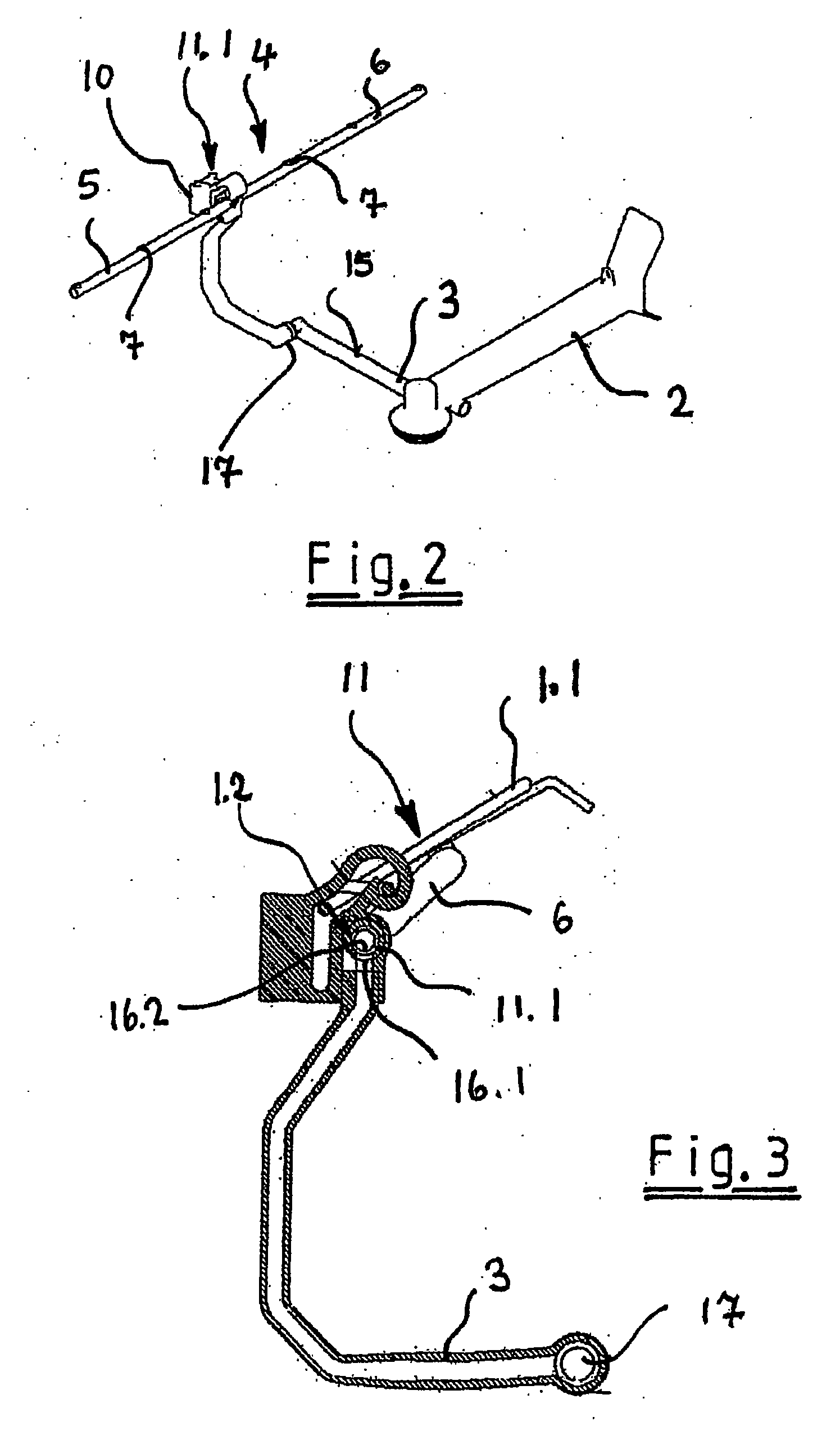
[0023] In accordance with a first embodiment, intensive washing zone 4 is preferably arranged beneath pivotable cup support 1.1 of rack 1, as is clearly shown in particular in FIG. 3 and FIG. 3.1. The two pipe elements 5 and 6 are supplied with wash water through a valve 11.1, said valve 11.1 itself being in communication with pipe branch 3. Actuator 11 is constituted by cup support 1.1 itself, so that pivoting the cup support 1.1 will open or close valve 11.1. As is apparent when viewing cross-sectional FIGS. 3 and 3.1 together, valve 11.1 is located in the region of swivel axis 1.2 of cup support 1.1, the valve 11.1 itself being formed by a pipe-in-pipe arrangement having openings 16.1 and 16.2 that are aligned with each other when in the pass-through position, as is illustrated in FIG. 3. The combined view in FIG. 3.1 shows how valve 11.1 closes when cup support 1.1 is pivoted upward. When cup support 1.1 is in this position, opening 16.2 is rotated with respect to opening 16.1 i...

second embodiment

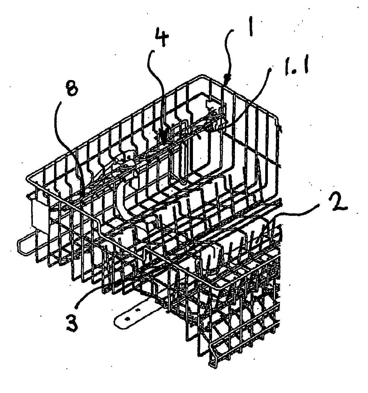
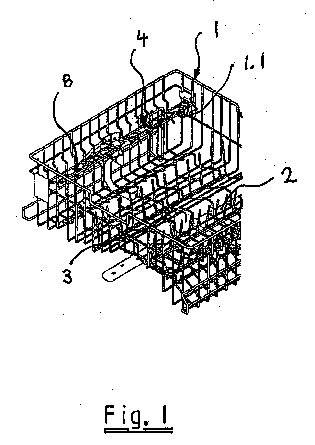
[0026]FIG. 4 shows a top view of a dish rack 1, here in particular the upper dish rack of a dishwasher. A feed tube 2 is in communication with dish rack 1, said feed tube supplying wash water to a spray arm, which is rotatably mounted beneath rack 1. At the end of feed tube 2, there is disposed a pipe branch 3 for an intensive washing zone 4 which is provided in the region of dish rack 1 and can be seen more clearly in FIG. 5, where the operative connection between intensive washing zone 4 and feed tube 2 can be clearly seen, in particular in the perspective view. It is apparent that when feed tube 2 is supplied with wash water by the circulating pump, intensive washing zone 4 is supplied with wash water through pipe branch 3 as well.

[0027] Intensive washing zone 4 is advantageously located beneath rack 1, as can be seen in particular from FIG. 4. Thus, the intensive washing zone does not cause any obstruction in the region of the upper rack holding system. Preferably, intensive wa...


PUM


Abstract

A dishwasher apparatus includes a dish rack having a wire member, and a feed tube for a spray arm rotatably disposed beneath the dish rack. An intensive washing zone is provided in a region of the dish rack, the intensive washing zone including a rod-shaped pipe element attached to the wire member and having an outlet nozzle. A pipe branch for the intensive washing zone is provided, the pipe branch being disposed in a region of the feed tube and communicating with the pipe element via a T-piece. An actuator is provided that cooperates with the pipe element so as to enable the intensive washing zone to be activated and deactivated.

Description

[0001] The present invention relates to a dish rack for a dishwasher, including a feed tube for a spray arm that is rotatably mounted beneath the rack, a pipe branch being disposed in the region of the feed tube, for an intensive washing zone provided in the region of the dish rack. BACKGROUND [0002] In dishwashers, items to be washed are held in at least one dish rack and acted upon by wash water from below and / or above. The wash water is supplied to the items to be washed, for example, via a rotatable spray arm mounted beneath the dish rack. The spray arm is supplied with wash water by a circulating pump, which circulates the wash water within the dishwasher. [0003] These prior art rotating nozzle arms produce so-called spray shadows, so that, especially in these regions, the spray jets issuing from the spray arm do not always effectively reach the items to be washed. Such a spray shadow occurs especially in the region of a two-level cup support (see, for example, DE 102004022024....

Claims


Application Information

Patent Timeline
Patent Type & Authority Applications(United States)
IPC IPC(8): B08B3/00A47L15/16A47L15/23A47L15/50
CPCA47L15/16A47L15/508A47L15/505A47L15/23
Inventor KOCH, STEPHANWEGENER, DIRK
Owner MIELE & CIE KG
Why Eureka
Try Eureka