Double-stop floating ball valve

a ball valve and double-stop technology, applied in the direction of valve details, valve arrangements, plug valves, etc., can solve the problems of blown out wellbore drilling fluid, other drilling structures, and other drilling structures, and the damage of drilling equipment, and the rig personnel may be seriously injured or killed, and the blowout of drilling fluid,

Inactive Publication Date: 2007-01-11
HYDRIL USA MANUFACTURING LLC
View PDF17 Cites 25 Cited by
  • Summary
  • Abstract
  • Description
  • Claims
  • Application Information

AI Technical Summary

Problems solved by technology

If the kick is allowed to reach the surface, drilling fluid, well tools, and other drilling structures may be blown out of the wellbore.
These “blowouts” often result in catastrophic destruction of the drilling equipment (including, for example, the drilling rig) and substantial injury or death of rig personnel.
One issue with this type of ball valve arrangement is that when the valve ball is in the second position, blocking flow through the passage, as seen in FIG. 1B, a force is being transmitted to the valve ball across the diameter of the valve ball, placing the valve ball under a compressive force.
The high stress may lead to deformation, crushing the ball.
After being deformed, when the valve ball is in the “closed” second position, the seal between the valve ball and the seats is undermined because of uneven contact between the seats and the valve ball.
An issue with having a ball valve arrangement with a spring loaded lower seat, as described above, is that the valve ball can only float in one direction.
However, such an assembly does not allow the ball to float in the upward direction.
Thus, when the valve ball is in its closed position and the fluid force coming from below the valve ball is too great, the valve ball will still deform from stress.
The valve ball deformation is because the ball valve arrangement does not provide an opening for the upward flowing fluid, fluid flowing opposite to the direction the valve ball is allowed to float in, to travel into the valve ball and redistribute the stresses on the valve ball.
For an IBOP, allowing pressure to transmit across the closed valve ball in either direction is undesirable.

Method used


Image

  • Double-stop floating ball valve
  • Double-stop floating ball valve
  • Double-stop floating ball valve

Examples


Embodiment Construction

[0027] The present invention relates to ball valve assemblies. More specifically, embodiments of the present invention provide high and low pressure sealing ability on both sides of the ball valve in a manner suitable for use in an IBOP.

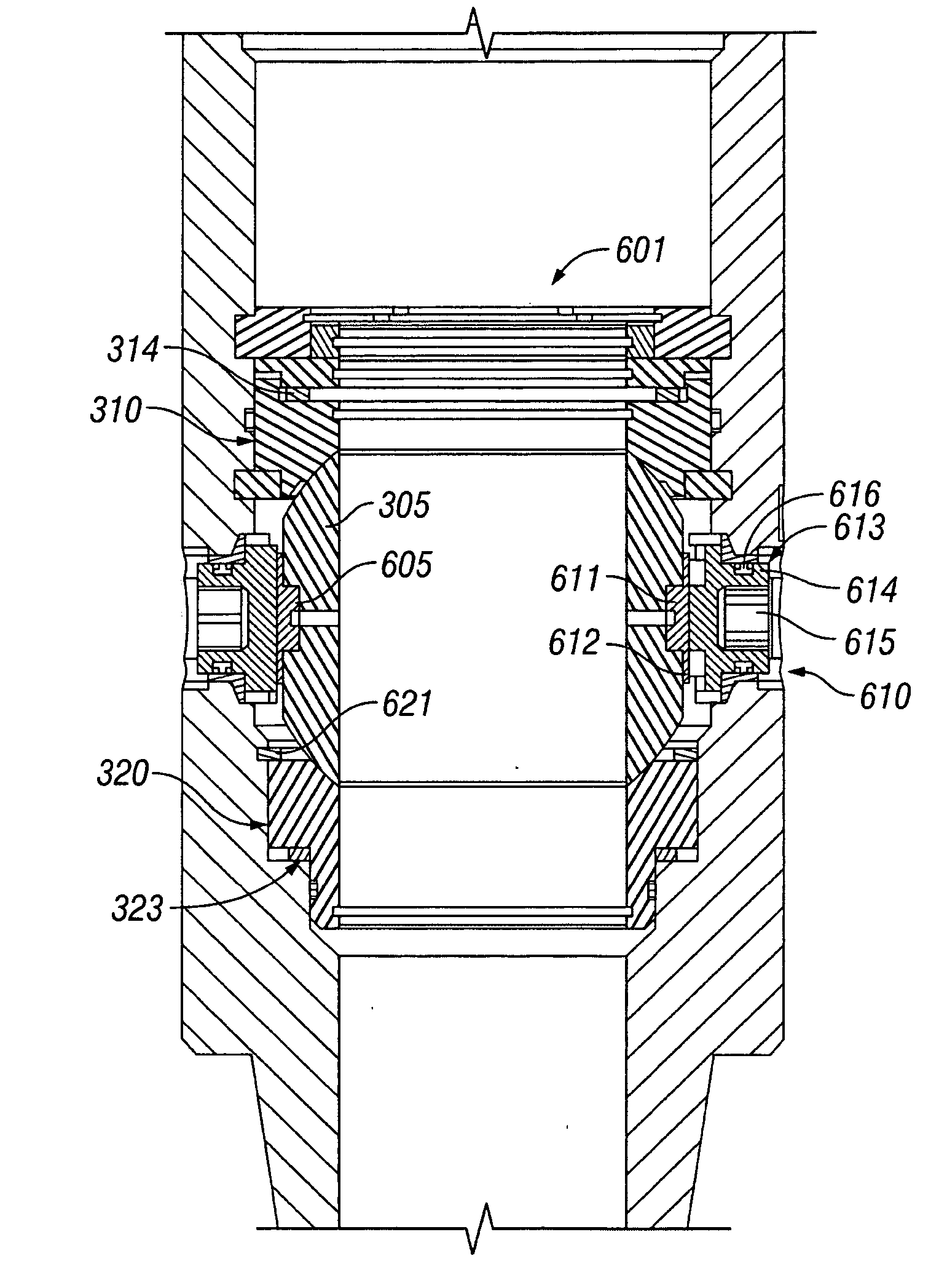
[0028]FIG. 3 is a cross-sectional view of a ball valve assembly 301, in accordance with one embodiment of the invention. The major components of the ball valve assembly 301 are a housing 350, an upper seat assembly 310, a lower seat assembly 320, a valve ball 305, and a spacer 332. In this embodiment, the housing 350 includes an upper passage section 351 and a lower passage section 352. The upper passage section 351 may be larger than the lower passage section 352.

[0029] In this embodiment, the lower seat assembly 320 may have an upper end 321 and a lower end 322. As shown, the lower end 322 is received in the lower passage section 352 by the housing 350. In this embodiment, the lower seat 320 sits on a biasing mechanism, in which the biasing mecha...


PUM


Abstract

Valve assemblies and methods of designing valve assemblies having a valve ball, an upper seat, and a lower seat. When fluid pressure is applied to the valve ball, the valve ball will float in the axial direction between an upper position, a neutral position, and a lower position in response to fluid pressure. The valve assembly may be made suitable for internal blowout preventers.

Description

BACKGROUND OF INVENTION [0001] 1. Field of the Invention [0002] The invention relates generally to blowout preventers used in the oil and gas industry. Specifically, the invention relates to a ball valve blowout preventer with two biasing seats, allowing the valve ball to float. [0003] 2. Background Art [0004] Well control is an important aspect of oil and gas exploration. When drilling a well, for example, in oil and gas exploration applications, safety devices must be put in place to prevent injury to personnel and damage to equipment resulting from unexpected events associated with the drilling activities. [0005] Drilling wells in oil and gas exploration involves penetrating a variety of subsurface geologic structures, or “layers.” Occasionally, a wellbore will penetrate a layer having a formation pressure substantially higher than the pressure maintained in the wellbore. When this occurs, the well is said to have “taken a kick.” The pressure increase associated with the kick is ...

Claims


Application Information

Patent Timeline
Patent Type & Authority Applications(United States)
IPC IPC(8): F16K5/06
CPCF16K5/0642F16K5/205F16K5/204
Inventor LEBLANC, JOHN R.FULTZ, JIMMYGUSTAFSON, RYAN
Owner HYDRIL USA MANUFACTURING LLC
Why Eureka
Try Eureka