
Illumination system and a display incorporating the same

a technology of a display and a display is applied in the field of a display and a display system, which can solve the problems of not providing a good private mode, and the effect of obscuring an image from anyone but the intended viewer, and achieves the effect of effective privacy

Inactive Publication Date: 2007-01-11
SHARP KK
View PDF32 Cites 111 Cited by
  • Summary
  • Abstract
  • Description
  • Claims
  • Application Information

AI Technical Summary

Benefits of technology

[0044] FIGS. 4(c) to 4(f) show the effect of varying the angle of inclination of the light-directing faces 408,416 of the prism 406. FIGS. 4(c) and 4(e) show a cross-section through the waveguide 404 for two different barrier layer characteristics and angles of inclination of the light-directing faces 408,416, with each angle of inclination being different from the angle of inclination of FIG. 4(a), and FIGS. 4(d) and 4(f) show the corresponding distributions of intensity against viewing angle. As FIGS. 4(d) and 4(f) show, while it is possible to change the angular position of zone 2 and zone 3 by varying the barrier layer characteristics and the angle of inclination, the angul...

Problems solved by technology

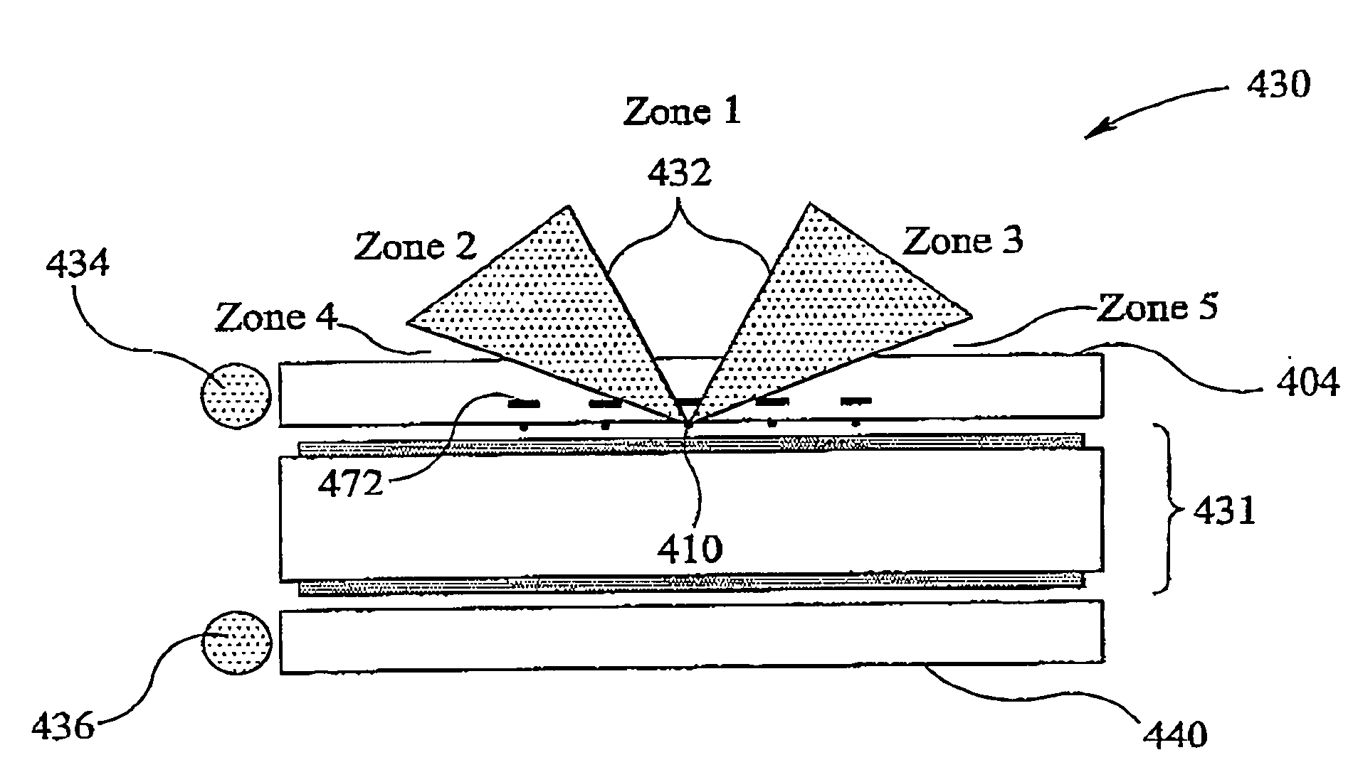
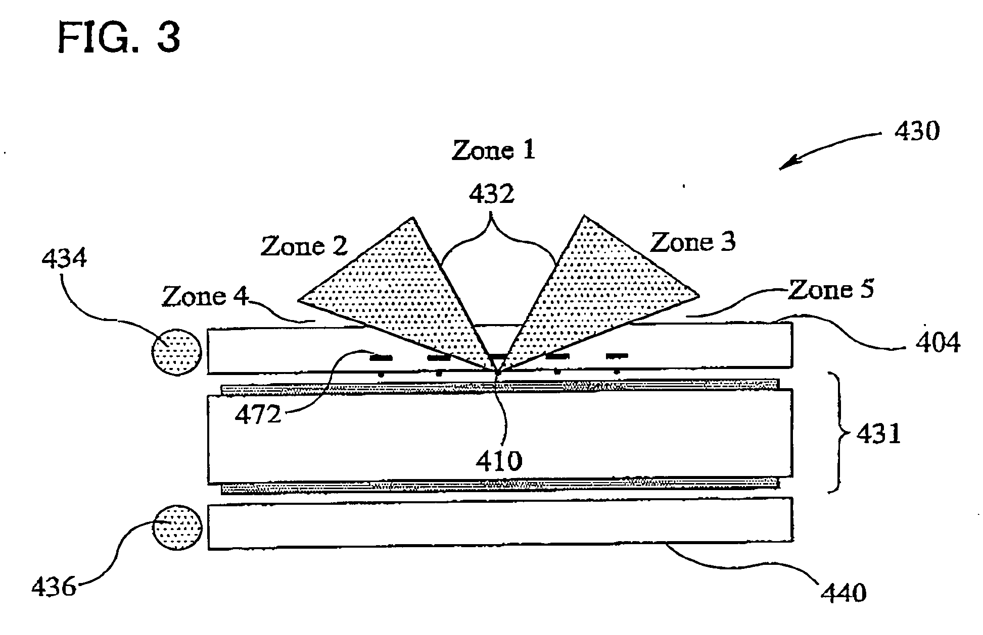
The display of FIG. 3 therefore has the disadvantage that it cannot provide a good private mode.
The private mode is therefore not effective at obscuring an image from anyone but the intended viewer.

Method used


Image

  • Illumination system and a display incorporating the same
  • Illumination system and a display incorporating the same
  • Illumination system and a display incorporating the same

Examples


Embodiment Construction

[0096]FIG. 5(a) is a schematic illustration of an illumination system according to an embodiment of the present invention. The illumination system comprises a waveguide 25 and one or more light sources 26. One light source 26 is shown in FIG. 5(a), but the invention is not limited to this.

[0097] Protrusions 27 are provided on a first surface 28 of the waveguide 28. As is explained above, light propagating within the waveguide is reflected by light-directing surfaces 29, 30 of the protrusion 27, and passes out of the surface 31 of the waveguide opposite to the surface 28 on which the protrusions 27 are provided.

[0098] The light-directing surfaces 29 direct light into a first angular range while directing substantially no light into a second angular range, the first angular range being different from the second angular range. The light directing surfaces 30 direct light into a third angular range while directing substantially no light into the second angular range. The third angular...


PUM


Abstract

An illumination system is providing comprising a first waveguide having a plurality of light-directing surfaces on its lower surface. These surfaces direct light through an output surface of the waveguide into at least one angular range while directing substantially no light into a different angular range. Each surface comprises a plurality of portions having different angles of inclination to a normal to the waveguide.

Description

[0001] This Nonprovisional application claims priority under U.S.C. § 119(a) on Patent Application No. 0513964.7 filed in U.K. on Jul. 8, 2005, the entire contents of which are hereby incorporated by reference. FIELD OF THE INVENTION [0002] The present invention relates to an illumination system for use in, for example, a display. The present invention also relates to a display incorporating an illumination system of the invention, and in particular to a display which is switchable between a private viewing mode and a public viewing mode. BACKGROUND OF THE INVENTION [0003] Electronic display devices, such as monitors used with computers and screens built in to telephones and portable information devices, are usually designed to have a viewing angle as wide as possible, so that they can be read from as many viewing positions as possible. However, there are some situations where it is useful to have a display that is visible from only a narrow range of angles. For example, where a per...

Claims


Application Information

Patent Timeline
IPC IPC(8): G02F1/1335F21V8/00G02F1/133G02F1/13357
CPCG02B6/0038G02B6/0056G02F1/133615G02B6/0061G02F1/1323G02B6/0058
Inventor LESAGE, ETIENNEMATHER, JONATHAN
Owner SHARP KK
Learn More