Wireless smart camera system and method

a smart camera and camera body technology, applied in the field of surveillance technology and equipment, can solve the problems of difficult installation and operation of wired devices, inability to provide secure wireless systems, time-consuming and laborious, etc., and achieve the effect of simple setup and control

Inactive Publication Date: 2007-01-11
SENSORMATIC ELECTRONICS CORP
View PDF33 Cites 64 Cited by
  • Summary
  • Abstract
  • Description
  • Claims
  • Application Information

AI Technical Summary

Benefits of technology

[0028] The present invention is directed to a wireless surveillance system and methods of operating same, providing simple setup and controls for high quality input capture by surveillance input capture devices (ICDs) that are capable of cross-communication with each other, including but not limited to video inputs, and digital input recorder device(s) (DIR) associated with the ICDs, the DIRs data transfer, storage, and control. More particularly, the present invention provides a wireless smart camera system and methods of using the same. The present invention is further directed toward systems and methods providing for remote viewing and controls of the ICDs and DIRs via a remote server computer (RSC) and / or Internet access through the RSC, the systems and methods having controllable communication between the ICD(s) and corresponding DIR.

Problems solved by technology

While video surveillance systems have existed in the prior art, typically they are wired devices that are difficult, time-consuming, and costly to install and operate.
Also, generally, they do not provide for wireless systems that are secure from wireless interception or Internet enabled interception and permit remote user access for viewing, reviewing stored information, and controlling the system's components, in particular via Internet connection to a remote controller computer or cellular phone or other Internet connected device.

Method used


Image

  • Wireless smart camera system and method
  • Wireless smart camera system and method
  • Wireless smart camera system and method

Examples


Embodiment Construction

[0048] In the following description, like reference characters designate like or corresponding parts throughout the several views. Also in the following description, it is to be understood that such terms as “forward,”“rearward,”“front,”“back,”“right,”“left,”“upwardly,”“downwardly,” and the like are words of convenience and are not to be construed as limiting terms.

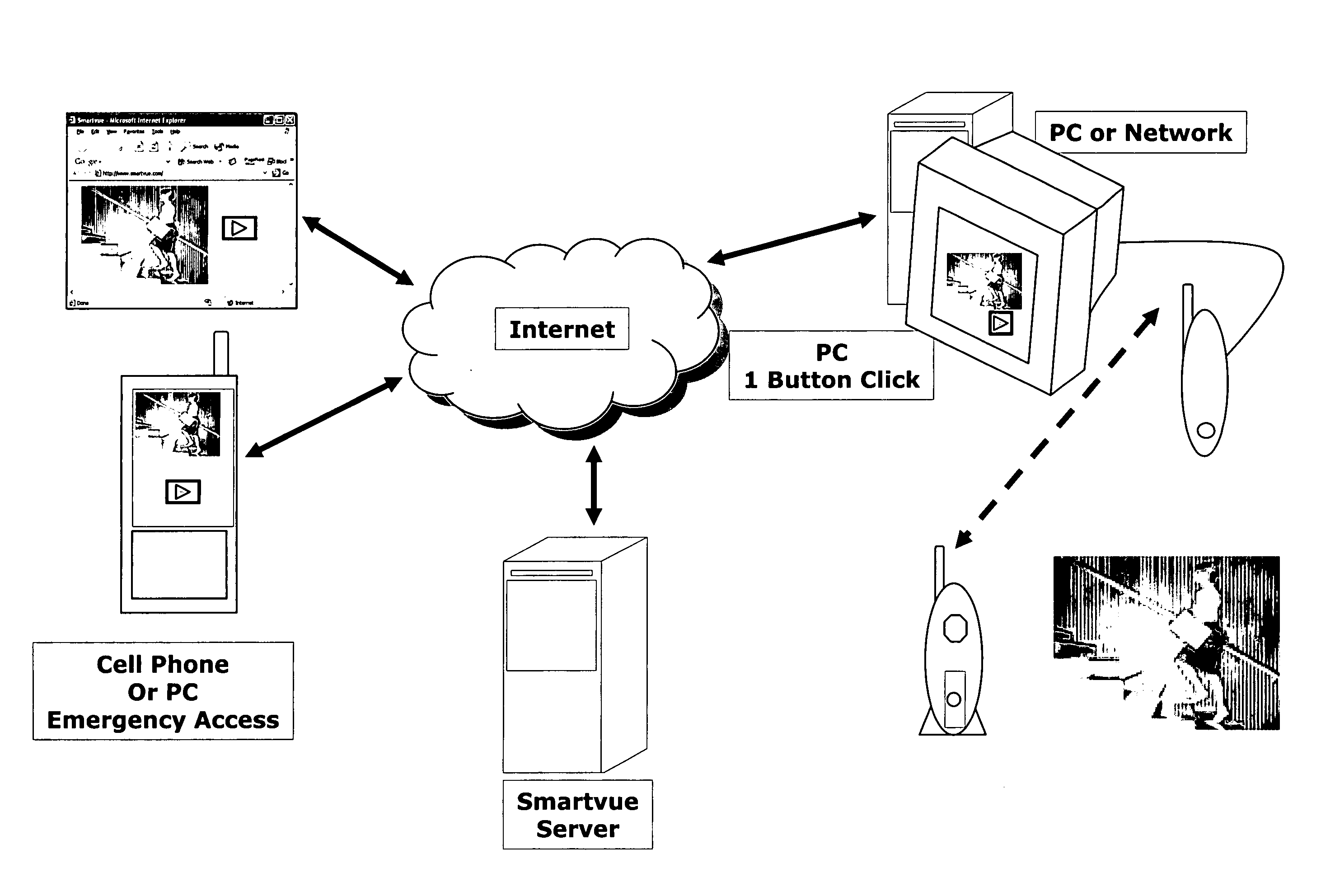
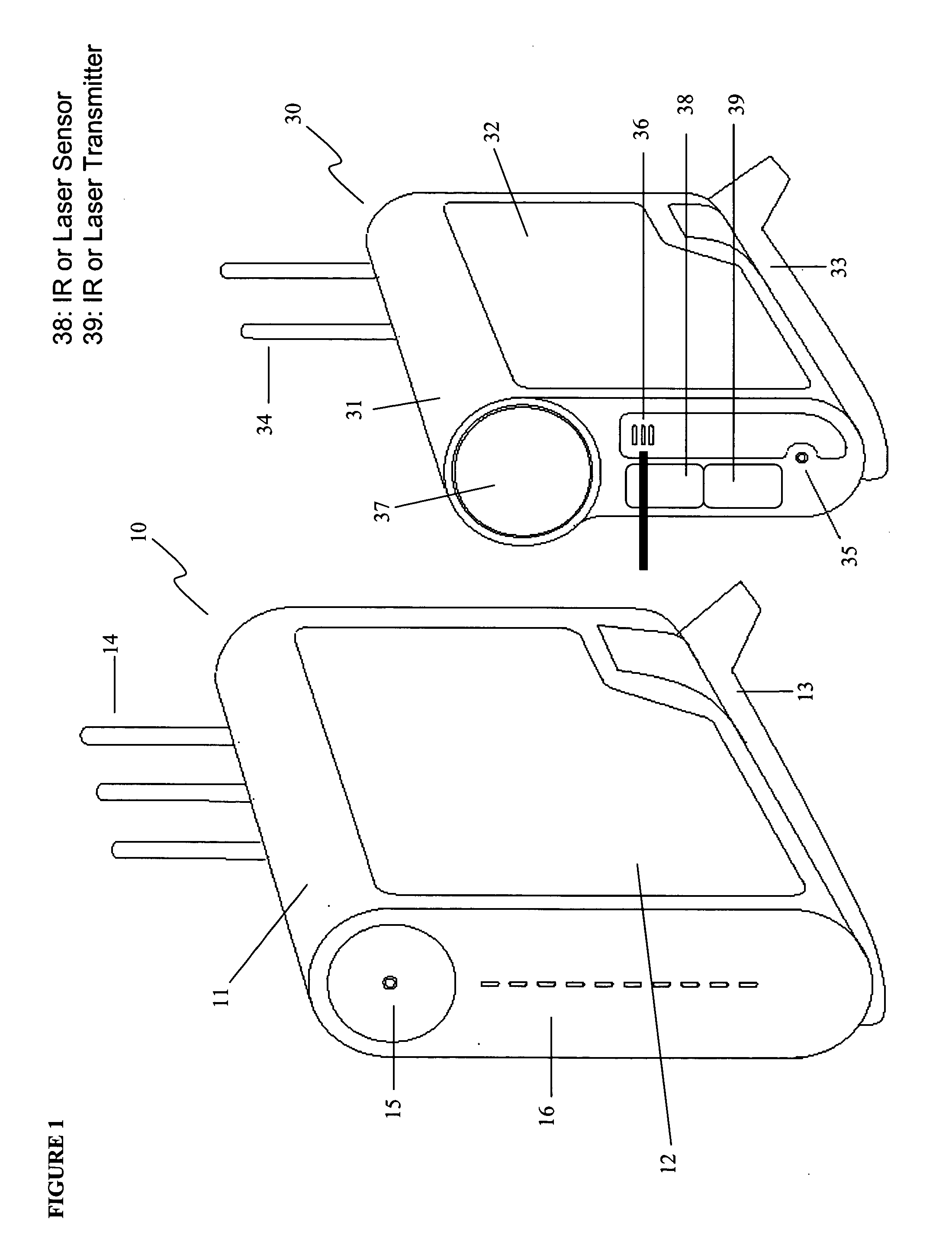
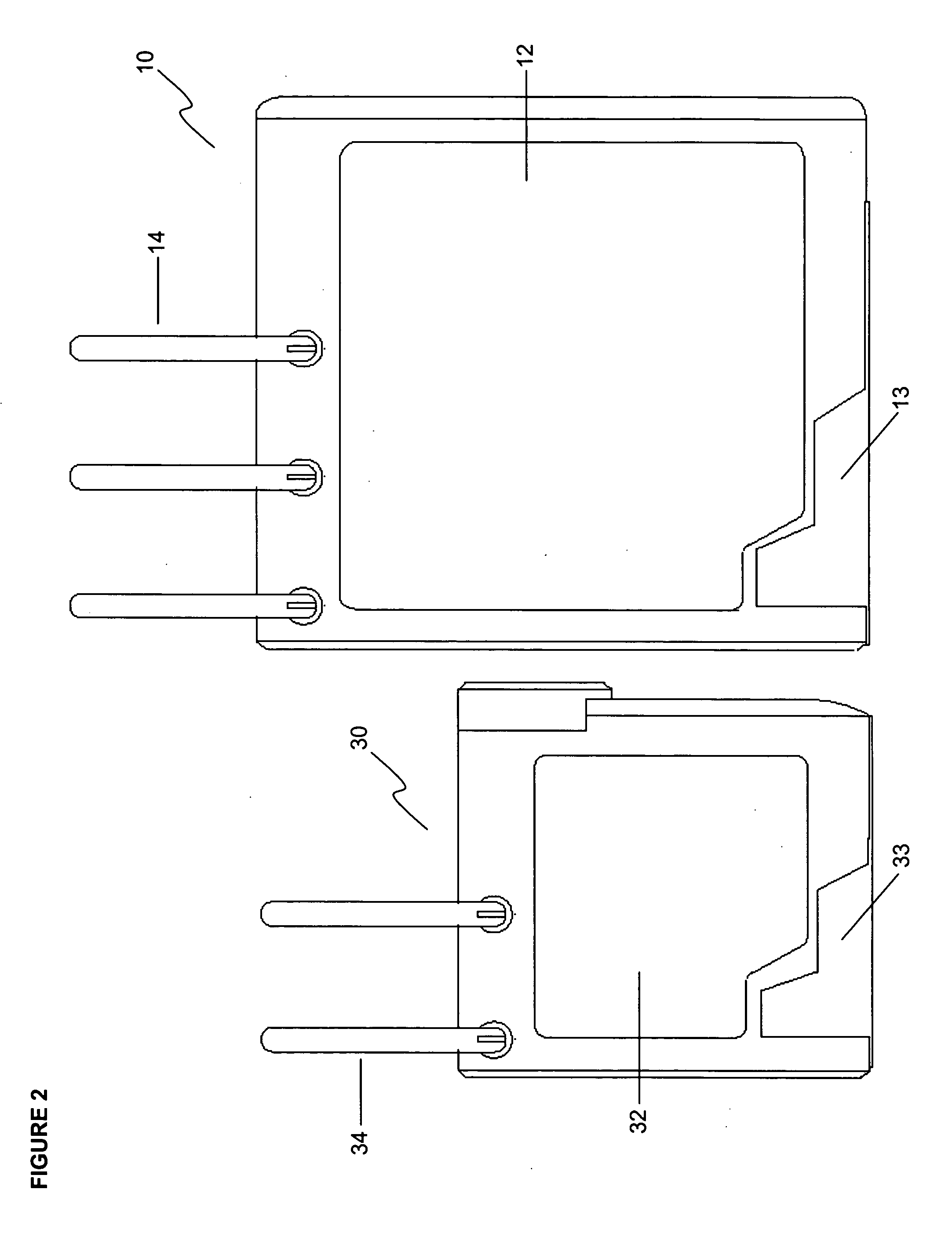
[0049] Referring now to the drawings in general, the illustrations are for the purpose of describing a preferred embodiment of the invention and are not intended to limit the invention thereto. As best seen in FIG. 1, the two base elements of a system constructed according to the present invention are shown side-by-side, including a wireless input capture device and a corresponding digital input recorder.

[0050]FIG. 1 shows a perspective view of one embodiment constructed according to the present invention, showing an input capture device (“ICD”), generally referred to as 30, and a digital input recorder (“DIR”), general...


PUM


Abstract

A smart mesh network surveillance system and method for providing communication between a base system having at least one wireless input capture device ICD(s) and other ICD(s), wherein the ICD(s) are capable of smart cross-communication with each other and remote access to their inputs via a server computer, including the steps of providing this base system; at least one user accessing the ICDs and inputs remotely via a user interface through a remote server computer and/or electronic device communicating with it, wherein the captured data is represented visually on a user interface or screen views for the user, the screen views showing 2-dimensional data and corresponding 3-dimensional data of the same input capture with coordinate overlay to provide a geographic context for the captured data.

Description

CROSS-REFERENCE TO RELATED APPLICATIONS [0001] This non-provisional utility patent application is related to one or more prior filed co-pending non-provisional applications: [0002] U.S. application Ser. No. 10 / 948,501, entitled “Wireless Video Surveillance System and Method With Two-Way Locking of Input Capture Devices,” filed on Sep. 23, 2004. [0003] U.S. application Ser. No. 10 / 949,487 entitled “Wireless Video Surveillance System & Method with DVR-Based Querying,” filed on Sep. 24, 2004. [0004] U.S. application Ser. No. 10 / 949,609 entitled “Wireless Video Surveillance System and Method with Emergency Video Access,” filed on. Sep. 24, 2004. [0005] U.S. application Ser. No. 10 / 950,033 entitled “Wireless Video Surveillance System and Method with Remote Viewing,” filed on. Sep. 24, 2004. [0006] U.S. application Ser. No. 10 / 949,489 entitled “Wireless Video Surveillance System and Method with External Removable Recording,” filed on. Sep. 24, 2004. [0007] U.S. application Ser. No. 10 / 949...

Claims


Application Information

Patent Timeline
Patent Type & Authority Applications(United States)
IPC IPC(8): H04K1/00
CPCG08B13/19615G08B13/19619G08B13/19621G08B13/19656G08B13/1966H04N7/185G08B13/19673G08B13/1968G08B13/19682G08B13/19691G08B13/19695G08B13/19663
Inventor RENKIS, MARTIN A.
Owner SENSORMATIC ELECTRONICS CORP
Why Eureka
Try Eureka