AC high voltage detecting device

Inactive Publication Date: 2007-01-18
SAMSUNG ELECTRONICS CO LTD
View PDF1 Cites 16 Cited by
  • Summary
  • Abstract
  • Description
  • Claims
  • Application Information

AI Technical Summary

Benefits of technology

[0022] The foregoing and/or other aspects of the present general inventive concept are also achieved by providing an image forming apparatus using an AC high voltage detecting device including a high voltage power supply (HVPS) to convert a low voltage into an AC high voltage, a rectifier to rectify the converted AC high voltage into a positive voltage and a negative voltage, a voltage divider to divide the rectified positive voltage and the rectified negative voltage into a first voltage and a second voltage, respectively, and a detector to read out a sum component of the first and the second voltages to detect the AC high voltage in a DC level.
[0023] The foregoing and/or other aspects of the present general inventive concept are also achieved by providing an AC high voltage detecting device usable with an image forming apparatus to detect a voltage level of an AC high voltage generated by a high voltage power supply (HVPS), including an AC-DC converter to convert the AC high voltage into a DC voltage, and a detector to detect a voltage level of the DC voltage and to determine the voltage level of the AC high voltage based on the detected voltage level of the DC voltage.
[0024] The foregoing and/or other aspects of the present general inventive concept are also achieved by providing an AC high voltage detecting device usable with an image forming apparatus to detect a voltage level of an AC high voltage generated by a high voltage power supply (HVPS), including a rectifying unit to rectify the AC high voltage into one or more DC voltages, a dividing unit to div

Problems solved by technology

However, the conventional high voltage detecting apparatus is likely to cause an error in sensing the high voltage due to an error that occurs by the oscilloscope 82 and the high voltage probe 81 when an AC voltage waveform is detected at an AC output terminal of the HVPS 70.
The occurrence of the error varies setting values and thus deteriorates image quality in the image forming apparatus.
Also, a time for restoring the varied setting values is additional required, which causes inefficiency of the image forming apparatus.

Method used


Image

  • AC high voltage detecting device
  • AC high voltage detecting device
  • AC high voltage detecting device

Examples


Embodiment Construction

[0032] Reference will now be made in detail to the embodiments of the present general inventive concept, examples of which are illustrated in the accompanying drawings, wherein like reference numerals refer to the like elements throughout. The embodiments are described below in order to explain the present general inventive concept by referring to the figures.

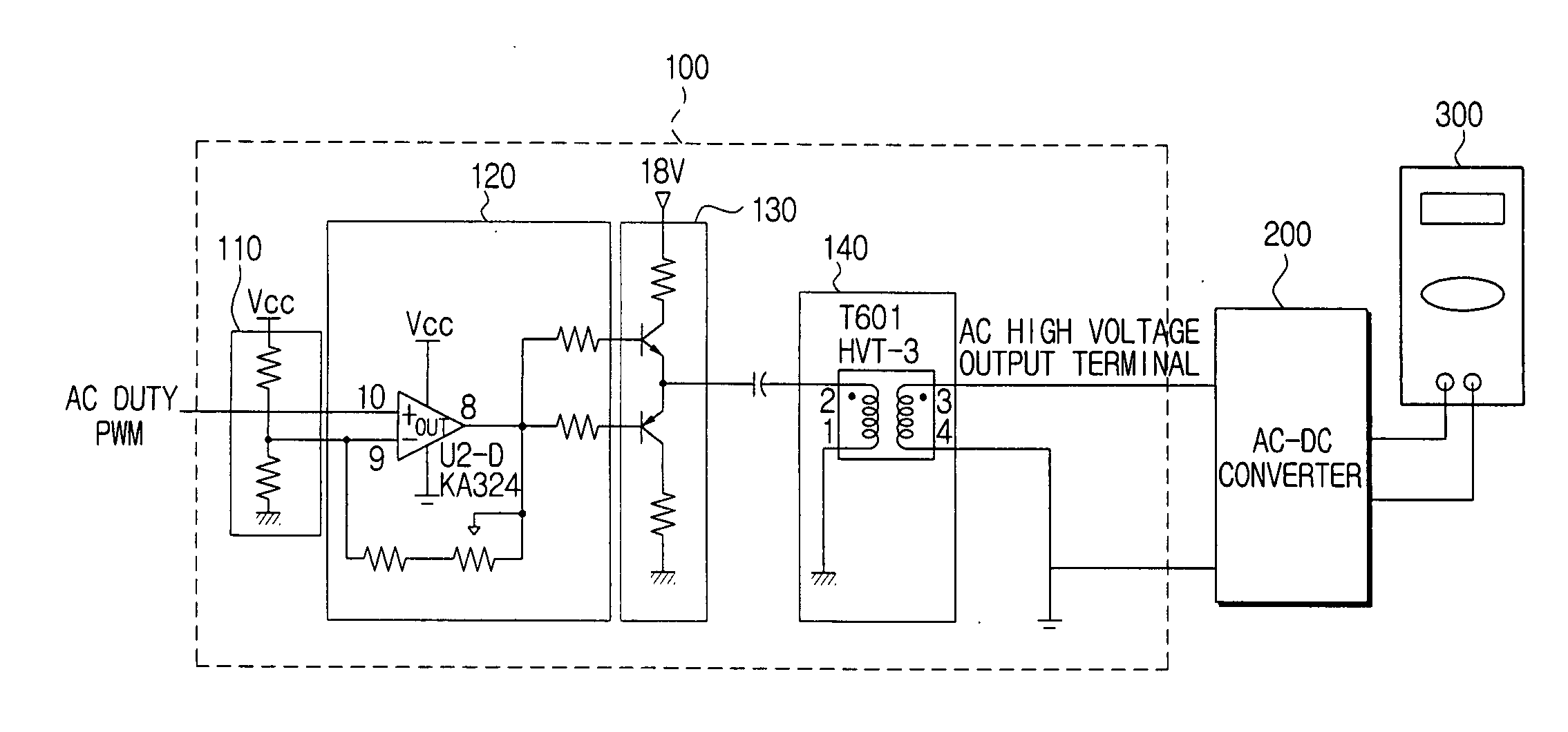
[0033]FIG. 3 is a circuit diagram illustrating an AC high voltage detecting device according to an embodiment of the present general inventive concept.

[0034] Referring to FIG. 3, the AC high voltage detecting device includes a high voltage power supply (HVPS) 100, an AC-DC converter 200, and a detector 300.

[0035] The HVPS 100 includes a pulse width modulation (PWM) input unit 110, comparator 120, a switching control unit 130, and a transformer 140. The HVPS 100 converts a low voltage into a high voltage of several hundreds to several thousands of volts and thereby can form a high voltage discharge on a drum of an image formi...


PUM


Abstract

An AC high voltage detecting device includes a high voltage power supply (HVPS) to convert a low voltage into an AC high voltage, a rectifier to rectify the converted AC high voltage into a positive voltage and a negative voltage, a voltage divider to divide the rectified positive voltage and the rectified negative voltage into a first voltage and a second voltage, respectively; and a detector to read out a sum component of the first and the second voltages to detect the AC high voltage in a DC level. Since the AC high voltage supplied from the high voltage power supply is detected after being converted into a DC voltage, there is no variance caused due to various devices required to detect an AC voltage.

Description

CROSS-REFERENCE TO RELATED APPLICATIONS [0001] This application claims benefit under 35 U.S.C. § 119 from Korean Patent Application No. 2005-63975, filed Jul. 15, 2005, the disclosure of which is incorporated herein in its entirety. BACKGROUND OF THE INVENTION [0002] 1. Field of the Invention [0003] The present general inventive concept relates to an AC high voltage detecting device usable with an image forming apparatus using a non-contact developing method. More particularly, the present general inventive concept relates an AC high voltage detecting device which converts an AC high voltage supplied from a high voltage power supply of an image forming apparatus into a DC voltage to detect the AC voltage. [0004] 2. Description of the Related Art [0005] An image forming apparatus prints an image corresponding to input original image data on a recording medium, such as paper. Examples of the image forming apparatus are printers, photocopiers, and facsimile machines. Laser beam printer...

Claims


Application Information

Patent Timeline
IPC IPC(8): H02M3/335
CPCH02M7/53803G01R19/165G03G15/00H02M7/10
Inventor OH, CHUL-WOOCHO, JONG-HWA
Owner SAMSUNG ELECTRONICS CO LTD
Why Eureka
Try Eureka