
Fiber optic tester

Inactive Publication Date: 2007-01-18
LAZO DANIEL OTONIEL
View PDF3 Cites 29 Cited by
  • Summary
  • Abstract
  • Description
  • Claims
  • Application Information

AI Technical Summary

Benefits of technology

[0034] The present invention is directed to fiber optic tester that may be used by a field technician for testing a variety and plurality or multiplicity of connectorized fiber optic cables and/or devices simultaneously. The fiber optic tester is quick, versatile, easy and simple to use, easily and quickly adaptable for use with different systems and configurations, inexpensive, long lasting, light weight, safe

Problems solved by technology

Although certain fiber optic testers have been available, such testers often do not allow for testing a plurality or multiplicity of fiber optic cables, terminations, and devices in the field, simultaneously.
Fiber optic testers that have been known are either capable of only testing a single connectorized termination, strand, or cable, are complicated or difficult to use in

Method used


Image

  • Fiber optic tester
  • Fiber optic tester
  • Fiber optic tester

Examples


Example

[0057] The preferred embodiments of the present invention will be described with reference to FIGS. 1-14 of the drawings. Identical elements in the various figures are identified with the same reference numbers.

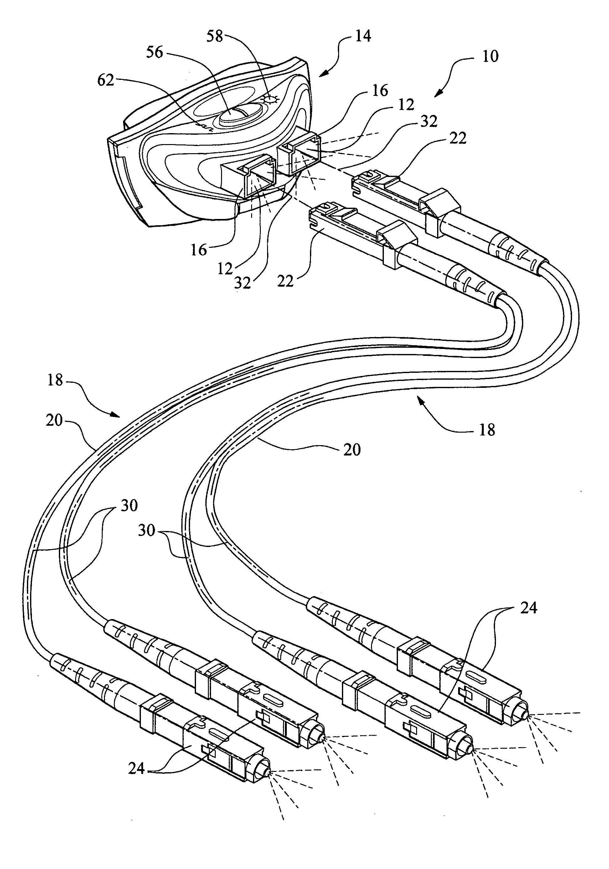
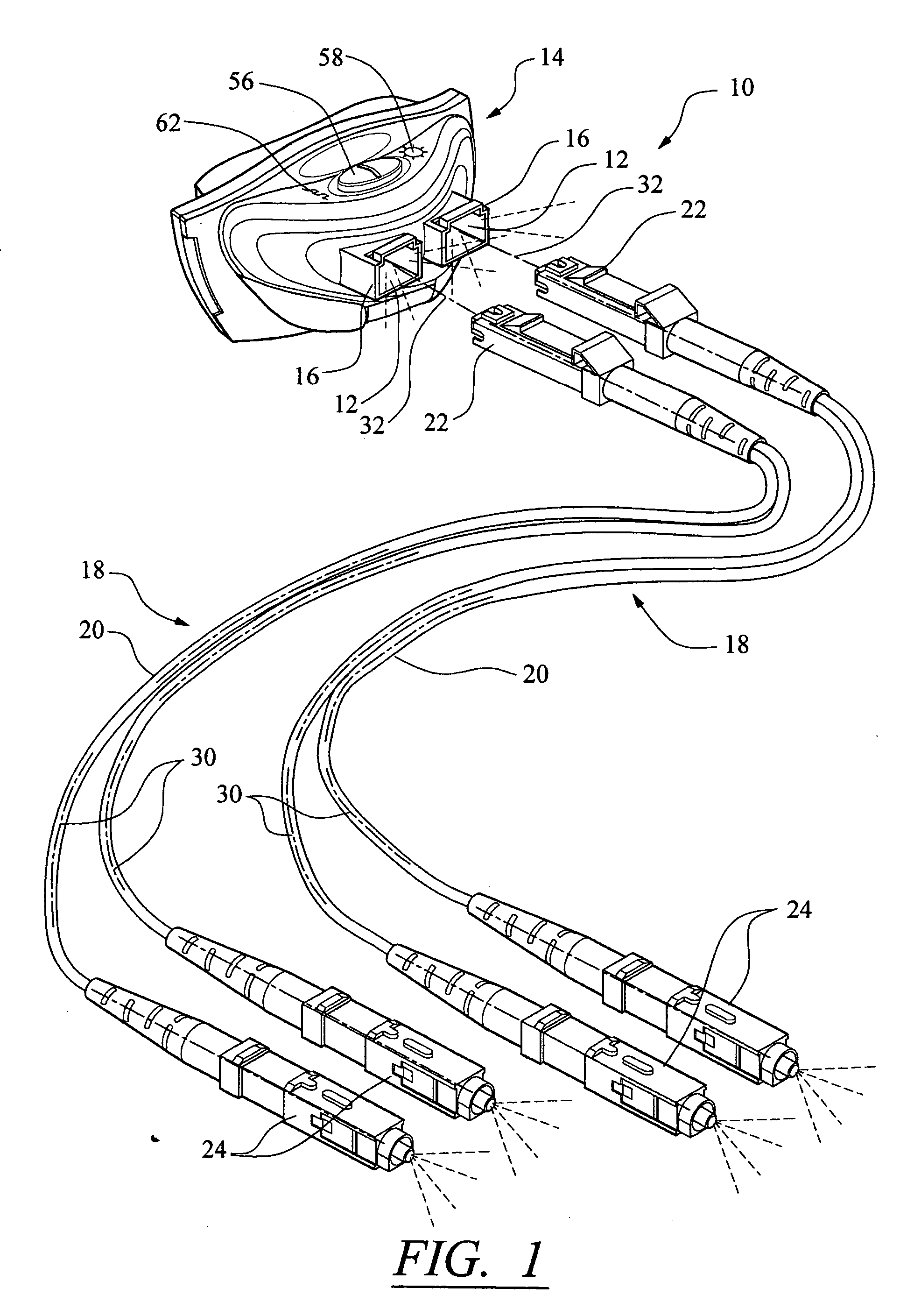
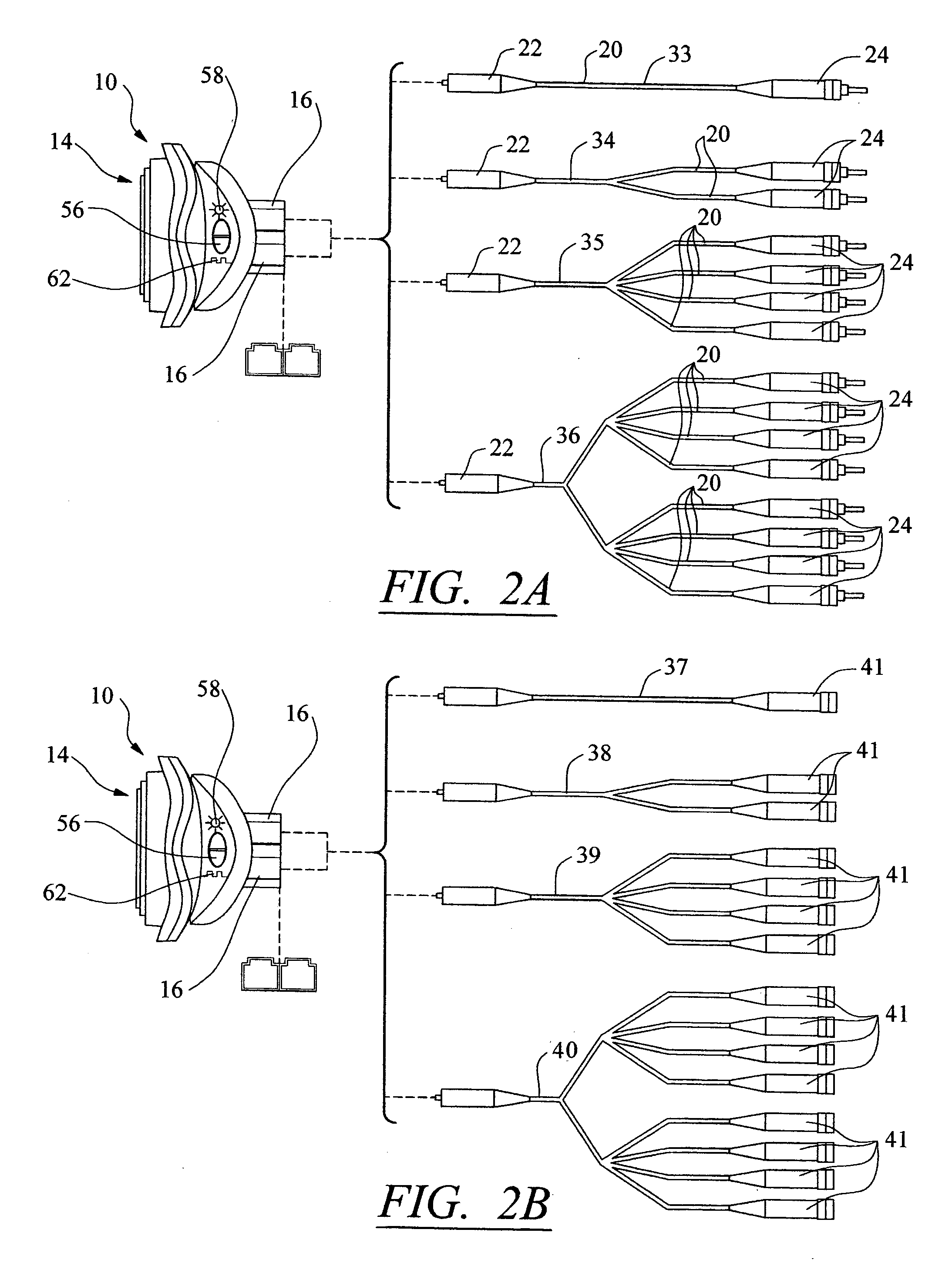
[0058]FIGS. 1-12 show an embodiment of the present invention, a fiber optic tester 10, comprising: a light source 12; a housing 14 having the light source 12 interiorly disposed thereto and housing connectors 16; and adapters 18. Each of the adapters 18 has an adapter fiber optic cable 20, a first connector 22 connected to the adapter fiber optic cable 20, and other connectors 24 opposingly connected to the adapter fiber optic cable 20. The first connectors 22 removably mate with the housing connectors 16, and the other connectors 24 are adapted to removably mate with fiber optic connectors 26 connected to fiber optic cables 28 and / or to removably mate with intermediate connectors 67, which mate with the fiber optic connectors 26, and / or to removably mate with a device or de...


PUM


Abstract

A fiber optic tester for testing at least two fiber optic devices substantially simultaneously, comprising: a housing having a light source and at least one housing connector, the light source interior to the housing; at least one adapter having at least one first connector and at least two second connectors, the at least one first connector removably and matingly connected to the at least one housing connector; the at least two second connectors adapted to removably and matingly connect to at least two fiber optic device input connectors; the fiber optic tester directing light into the at least two fiber optic device input connectors, when the at least two second connectors are removably matingly connected to the at least two fiber optic device input connectors, the presence and/or absence of light from output connectors of the at least two fiber optic devices indicating the condition of the fiber optic devices.

Description

BACKGROUND OF THE INVENTION [0001] 1. Field of the Invention [0002] The present invention relates generally to fiber optic testers and more particularly to fiber optic testers that may be used in the field. [0003] 2. Background Art [0004] Fiber optic cables are used in many systems for transmission of broad bandwidth digital and analogue signals, and are currently in prolific use in networks of all kinds, such as the internet, wide area networks, local area networks, cable, communications, and telecommunications systems. Fiber optic cables have become the transmission medium of choice for these systems. [0005] Construction, testing, installation, and maintenance of fiber optic systems requires equipment that may be used in the field to test the fiber optic cables in a variety of installations and different circumstances. Although certain fiber optic testers have been available, such testers often do not allow for testing a plurality or multiplicity of fiber optic cables, termination...

Claims


Application Information

Patent Timeline
IPC IPC(8): G02B6/00
CPCG01M11/30G02B6/4469G01M11/33
Inventor LAZO, DANIEL OTONIEL
Owner LAZO DANIEL OTONIEL
Learn More