Energy conversion systems utilizing parallel array of automatic switches and generators
What is AI technical title?
AI technical title is built by Patsnap AI team. It summarizes the technical point description of the patent document.
a technology of automatic switch and energy conversion system, which is applied in the direction of generator/motor, mechanical apparatus, combustion engine, etc., can solve the problems of paddles oscillation, reduce the speed of individual molecules, reduce thermal energy, and efficiently collect and sum outputs
Inactive Publication Date: 2007-01-25
CJP IP HLDG
View PDF14 Cites 25 Cited by
Summary
Abstract
Description
Claims
Application Information
AI Technical Summary
This helps you quickly interpret patents by identifying the three key elements:
Problems solved by technology
Method used
Benefits of technology
Benefits of technology
[0011] The nanometer scale electromechanical systems of the present invention efficiently convert molecular-level energy from one form into another form by reducing the velocity of the molecules within the working substance. These systems may include, for example, a heat engine that converts molecular-level heat energy into useful mechanical or electrical energy. Such systems may also include a heat pump that utilizes molecular-level energy to either heat or cool a substance. For example, a system of the present invention may be mounted to a microprocessor as the primary cooling device, so that little or no fans would be necessary. In addition, these systems may also include propulsion systems in which molecular-level energy is utilized to create a pressure differential on the surface of an object, thereby providing the ability to propel that object in a controllable direction.
[0013] The nanometer-sized paddles, in conjunction with an associated generator, reduce the speed of individual molecules which results in a reduction of thermal energy within the working fluid. The generated electrical energy may be converted back to thermal energy at a higher temperature than the working fluid and used to establish a temperature differential that is capable of performing useful work. Essentially, the paddles are configured to be immersed in a working substance. The paddles move in a random manner within the working substance due to variations in the thermal motion of the molecules of the working substance. This movement necessarily results from collisions between the molecules of the working substance and the paddles which are large enough to cause the paddles to oscillate. The kinetic energy from this oscillation may then be converted into electrical, electromagnetic or thermal energy by various methods, as described above.
[0014] Nanometer scale electromechanical systems constructed in accordance with the present invention also provide components that efficiently collect and sum the outputs of the numerous paddles so that a useful electrical output is produced. For example, one embodiment of the present invention includes the use of an array of resistive elements, one for each paddle, that are in contact with one side of the thermocouple. The other side of the thermocouple is placed in thermal contact with something else that is at an ambient temperature (such as a gas or liquid). Each of the thermocouples produces an output (i.e., a DC current and voltage) that can be summed through a simple series connection to produce an output, depending on the number of paddles and configuration, on the order of several milliwatts.
Problems solved by technology
This movement necessarily results from collisions between the molecules of the working substance and the paddles which are large enough to cause the paddles to oscillate.
Method used
Image
Click on the blue label to locate the original text in one second.
Reading with bidirectional positioning of images and text.
Examples
Embodiment Construction
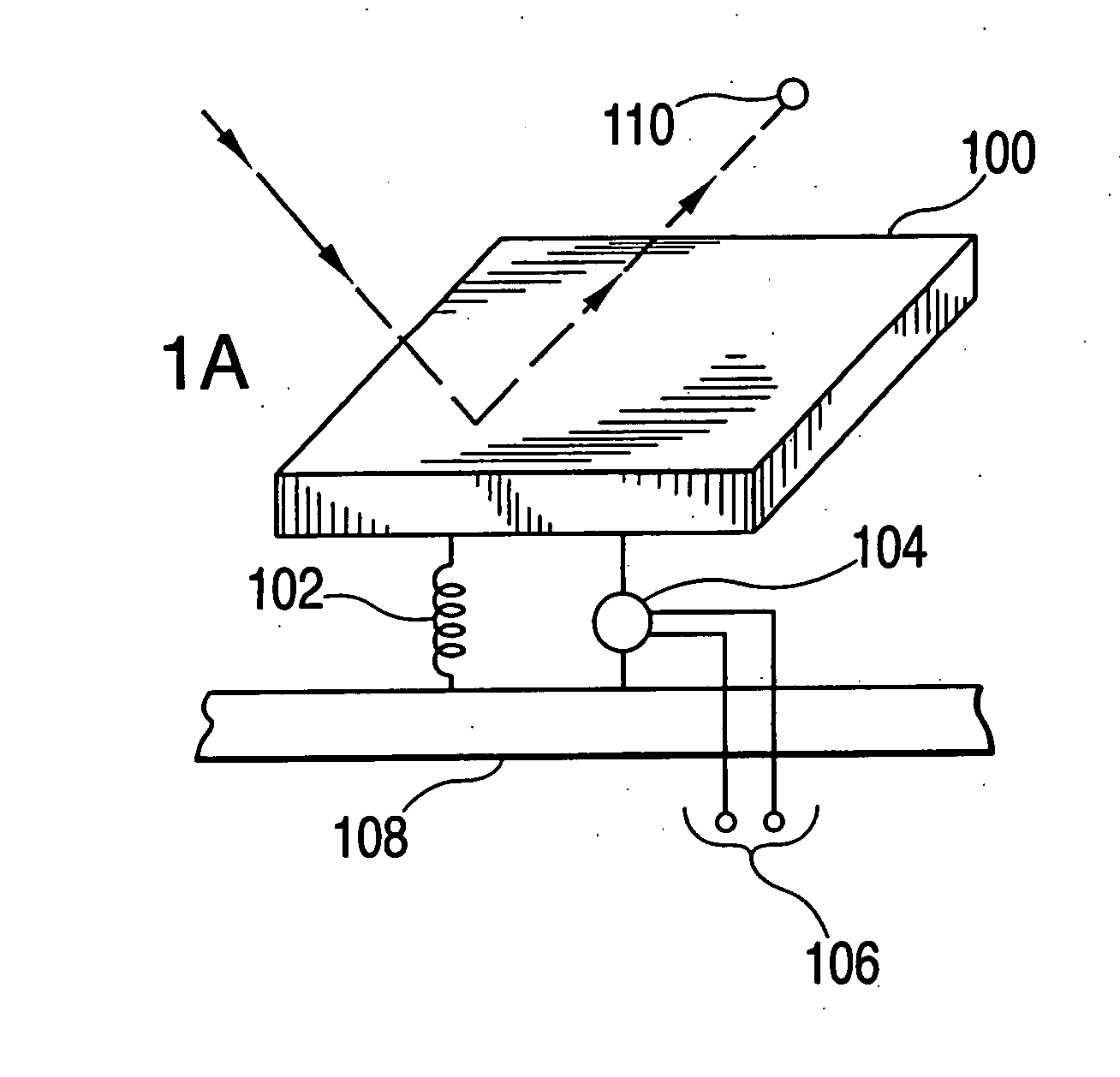
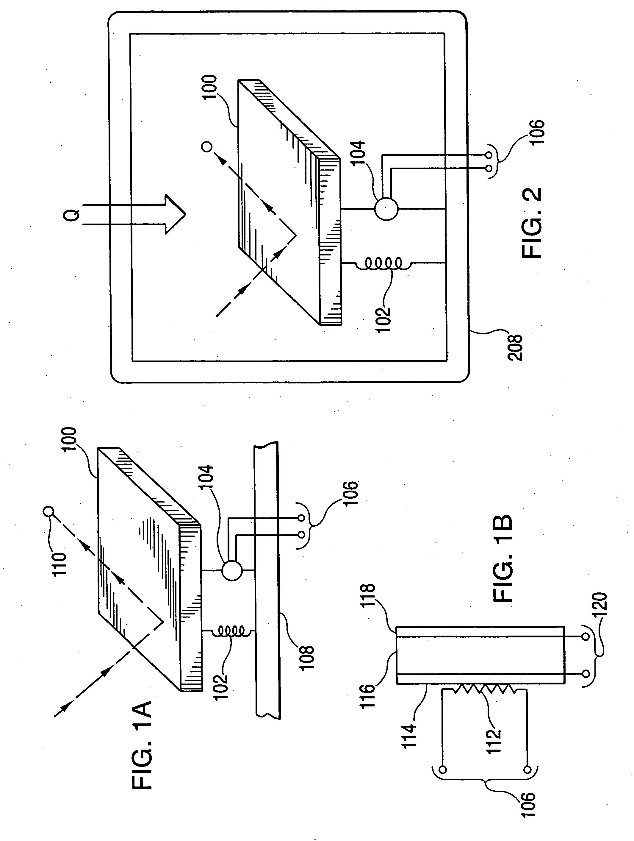
[0049]FIG. 1A shows an illustrative example of a portion of a nanometer scale electromechanical system constructed in accordance with the present invention. The portion shown includes an impact mass in the form of paddle 100, a restraining member 102, an generator device 104 (which provides an electrical output at leads 106), and a base 108 (which is typically thousands or millions times larger than paddle 100). Paddle 100 is attached to base 108, which may be thermally conductive, but need not be, so that paddle 100 may be moved within a predetermined range of distance in one or more directions (such as laterally, or up and down). A complete energy conversion system using nanometer scale assemblies would typically include a million or more of the devices shown in FIG. 1A, as will become more apparent below (see, for example, FIGS. 5 and 6).
[0050] Paddle 100 may be constructed, for example, from a substance such as carbon or silicon, although persons skilled in the art will appreci...
PUM
Abstract
Nanoelectromechanical systems utilizing nanometer-scale assemblies are provided that convert thermal energy into another form of energy that can be used to perform useful work at a macroscopic level. These systems may be used to, for example, produce useful quantities of electric or mechanical energy, heat or cool an external substance or propel an object in a controllable direction. In particular, the present invention includes nanometer-scale beams that reduce the velocity of working substance molecules that collide with this nanometer-scale beam by converting some of the kinetic energy of a colliding molecule into kinetic energy of the nanometer-scale beam. In embodiments that operate without a working substance, the thermal vibrations of the beam itself create the necessary beam motion. In some embodiments, an automatic switch is added to realize a regulator such that the nanometer-scale beams only deliver voltages that exceed a particular amount. Various devices including, piezoelectric, electromagnetic and electromotive force generators, are used to convert the kinetic energy of the nanometer-scale beam into electromagnetic, electric or thermal energy. Systems in which the output energy of millions of these devices is efficiently summed together are also disclosed as well as systems that include nanometer-scale transistors.
Description
BACKGROUND OF THE INVENTION [0001] This invention relates to nanometer scale electromechanical systems. In particular, the present invention relates to nanometer scale electromechanical systems that may be used in various applications, such as heat engines, heat pumps, or propulsion systems. [0002] Electromechanical systems that rely on molecular motion are known. For example, U.S. Pat. No. 4,152,537 (the “'537 patent”), describes an electricity generator that produces electrical energy from the random movement of molecules in a gas, and the uneven distribution of thermal energy in different molecules of the gas, which is at an overall uniform temperature. [0003] Other such systems are described in, for example, U.S. Pat. Nos. 3,365,653; 3,495,101, 2,979,551; 3,609,593; 3,252,013 and 3,508,089. These systems produce electricity or devices driven by electricity, such as an oscillator, based on molecular motion and thermal energy. [0004] One problem common to all of these systems is t...
Claims
Application Information
Patent Timeline
Application Date:The date an application was filed.
Publication Date:The date a patent or application was officially published.
First Publication Date:The earliest publication date of a patent with the same application number.
Issue Date:Publication date of the patent grant document.
PCT Entry Date:The Entry date of PCT National Phase.
Estimated Expiry Date:The statutory expiry date of a patent right according to the Patent Law, and it is the longest term of protection that the patent right can achieve without the termination of the patent right due to other reasons(Term extension factor has been taken into account ).
Invalid Date:Actual expiry date is based on effective date or publication date of legal transaction data of invalid patent.
Patent Type & AuthorityApplications(United States)

