Switch with fully isolated power sourcing equipment control

a technology of power sourcing equipment and switch, applied in the field of electrical equipment, can solve the problems of not having electrical isolation to protect the rest of the pd devices from a lightening strike near any one of the pd devices, and providing a certain level of operating functionality for modules,

Inactive Publication Date: 2007-01-25
AVAGO TECH INT SALES PTE LTD
View PDF38 Cites 32 Cited by
  • Summary
  • Abstract
  • Description
  • Claims
  • Application Information

AI Technical Summary

Benefits of technology

[0020] In one embodiment, the present invention is an apparatus having an isolated side and a line side. The apparatus comprises a physical-layer module, a power switcher, a power conditioning module, and a control module. The physical-layer module is (1) located on the isolated side of the apparatus, (2) adapted to be electrically coupled via a signal-isolation transformer to a cable connector located on the line side of the apparatus, and (3) adapted to process signals transmitted over the cable. The power switcher is located on the isolated side of the apparatus. The power conditioning module is (1) located on the line side of the apparatus, (2) electrically coupled to the power switcher via a power-isolation transformer adapted to convert an AC power signal received from the power switcher into a transformed AC power signal, and (3) adapted to convert the transformed AC power signal into a cable power signal to be supplied via the connector to the cable in order to power a cable-powered device connected to the cable. The control module is located on the isolated side of the apparatus and adapted to perform a detection function in which the control module determines whether or not a cable-powered device is connected to the cable.

Problems solved by technology

These conventional PSE control and power conditioning modules provide a certain (relatively limited) level of operating functionality.
First of all, there is a considerable dollar cost to providing all of this circuitry associated with these functions.
Furthermore, when two or more PD devices are connected to different Ethernet connectors supported by a single line-side PSE control and power conditioning module, there is no electrical isolation to protect the rest of the PD devices from a lightening strike near any one of the PD devices.

Method used


Image

  • Switch with fully isolated power sourcing equipment control
  • Switch with fully isolated power sourcing equipment control
  • Switch with fully isolated power sourcing equipment control

Examples


Embodiment Construction

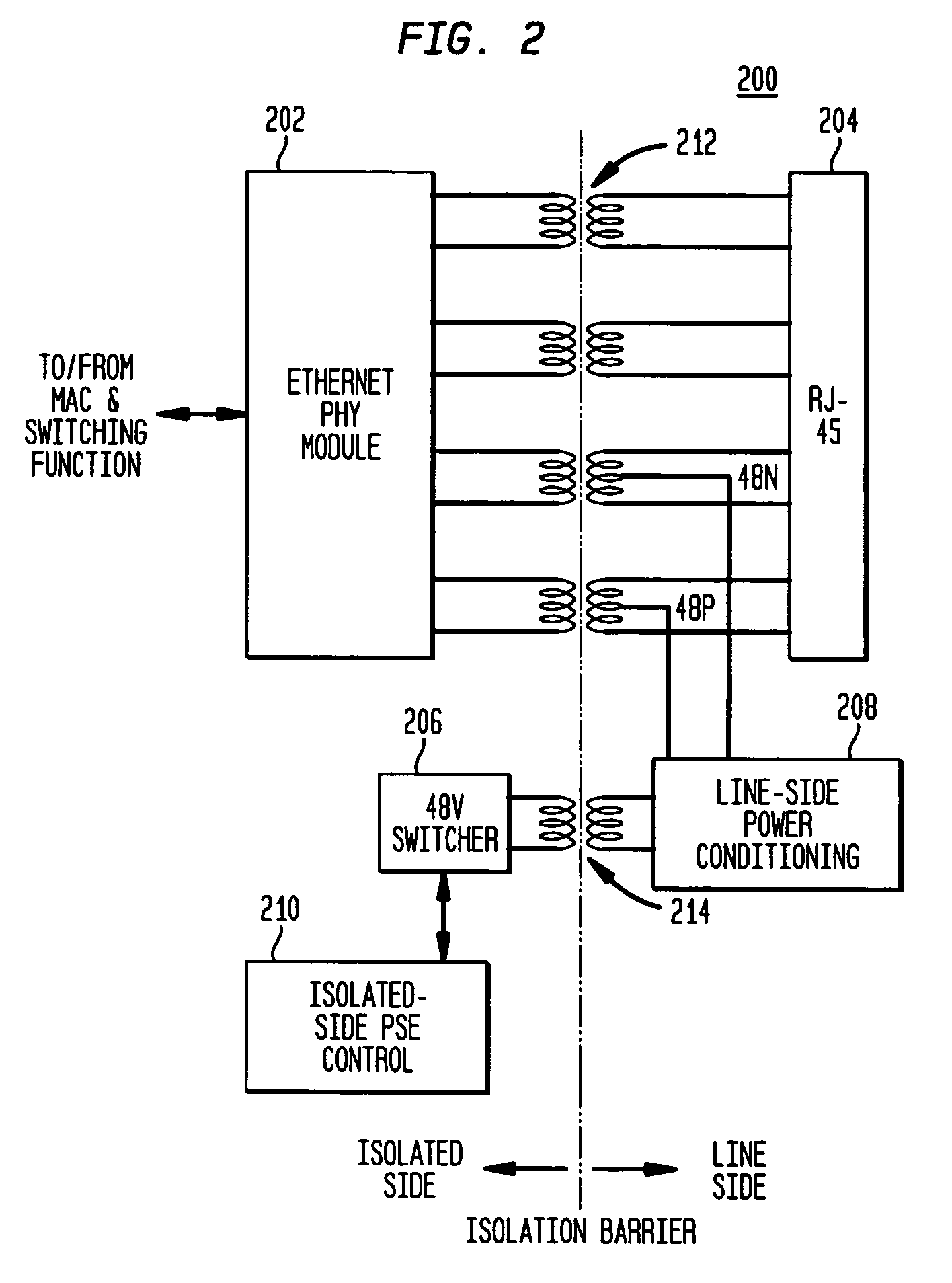
[0032]FIG. 2 shows a block diagram of a portion of an Ethernet switch 200 for a communication system that conforms to the IEEE 802.3 Ethernet and the IEEE 802.3af Power over Ethernet (PoE) standards, according to one embodiment of the present invention. As shown in FIG. 2, Ethernet switch 200 comprises Ethernet PHY module 202, RJ-45 Ethernet connector 204, 48-volt switcher 206, line-side PSE power conditioning module 208, isolated-side PSE control module 210, four-pair signal-isolation transformer 212, and power-isolation transformer 214, where switcher 206 and power conditioning module 208 function together as an isolated switching power supply. Ethernet PHY module 202, connector 204, and transformers 212 and 214 are similar to the corresponding elements in conventional switch 100 of FIG. 1. Note that, unlike switch 100 of FIG. 1, switch 200 does not have any optical isolator.

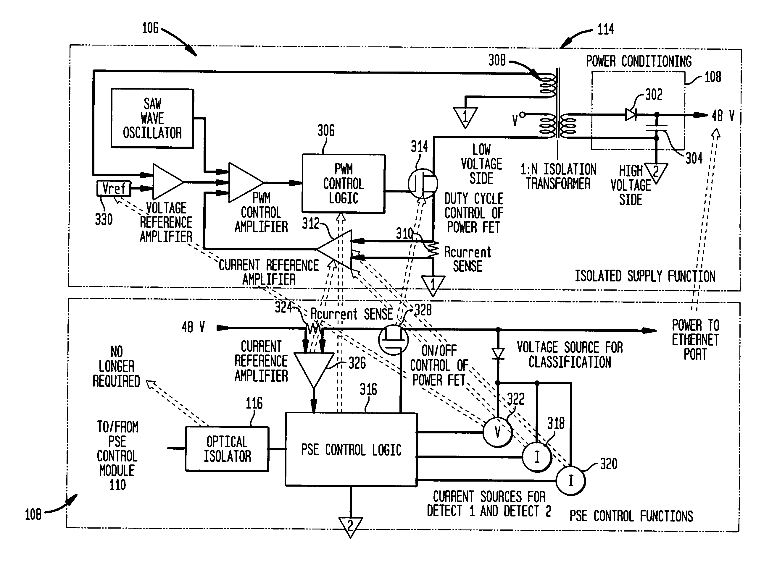
[0033] According to this embodiment of the present invention, the PSE detection and (optional) classificat...


PUM


Abstract

In one embodiment, the invention is an apparatus (e.g., an Ethernet switch) having an isolated side and a line side. A line-side connector is connectable to a cable. An isolated-side physical-layer module (1) is electrically coupled to the connector via a signal-isolation transformer and (2) processes signals transmitted over the cable. A line-side power conditioning module (1) is electrically coupled to an isolated-side power switcher via a power-isolation transformer that converts an AC power signal received from the power switcher into a transformed AC power signal and (2) converts the transformed AC power signal into a cable power signal to be supplied via the connector to the cable in order to power a cable-powered device connected to the cable. An isolated-side control module performs a detection function in which the control module determines whether or not a cable-powered device is connected to the cable.

Description

CROSS-REFERENCE TO RELATED APPLICATIONS [0001] This application claims the benefit of the filing date of U.S. provisional application No. 60 / 706,512, filed on Jul. 21, 05 as attorney docket no. Blaha 5-2, the teachings of which are incorporated herein by reference.BACKGROUND OF THE INVENTION [0002] 1. Field of the Invention [0003] The present invention relates to electronics, and, in particular, to Power Sourcing Equipment (PSE) for communication systems conforming to the IEEE 802.3 Ethernet and IEEE 802.3af Power over Ethernet (PoE) standards. [0004] 2. Description of the Related Art [0005]FIG. 1 shows a block diagram of a portion of a conventional Ethernet switch 100 for a communication system that conforms to both the IEEE 802.3 Ethernet standard and the IEEE 802.3af PoE standard, the teachings of both of which are incorporated herein by reference. As shown in FIG. 1, for each port in the switch, Ethernet switch 100 comprises Ethernet Physical-Layer (PHY) module 102, RJ-45 Ethern...

Claims


Application Information

Patent Timeline
Patent Type & Authority Applications(United States)
IPC IPC(8): H02M3/335
CPCH02M3/33523
Inventor BLAHA, MATTHEWQUIRK, PATRICK J.
Owner AVAGO TECH INT SALES PTE LTD
Why Eureka
Try Eureka