
Distributed intercom system

a technology of intercom system and audio, applied in the direction of interconnection arrangement, electrical apparatus, substation equipment, etc., can solve the problems of low sound quality, bulky and obtrusive prior art systems, and present intercom systems

Inactive Publication Date: 2010-07-27
LEGRAND HOME SYST +1
View PDF36 Cites 41 Cited by
  • Summary
  • Abstract
  • Description
  • Claims
  • Application Information

AI Technical Summary

Problems solved by technology

However, the presently existing intercom systems have several drawbacks.
In addition, these prior art systems are often bulky and obtrusive.
For example, most prior art systems will distribute an audio signal over a dedicated line to the speaker at the remote unit, such that the audio signal is weakened and degraded during communication, resulting in a distorted, low-quality sound.
Accordingly, these systems are both expensive and intrusive in both the residential and commercial environments.
While such home automation systems, which may include an intercom feature, allow for the control of the digital audiovisual signals throughout an enclosed structure, the complexity of installation is matched only by the complex, difficult and time-consuming maintenance of such extensive systems.
Still further, many prior art systems include central control units that have no indicators of activity at the remote unit locations, e.g., outgoing or incoming calls, such that a user cannot identify and specifically locate certain activities.
While selective-call intercom systems exist, such systems are rarely used and are expensive to install and operate.
Accordingly, these prior art systems have no integration between the intercom system and other systems, such as multi-room audio, telephones and / or other communication systems.
Finally, many prior art systems are difficult to install and require the attachment of an oftentimes unsightly central or remote unit on the wall of the residence or structure.

Method used


Image

  • Distributed intercom system
  • Distributed intercom system
  • Distributed intercom system

Examples


Embodiment Construction

[0034]For purposes of the description hereinafter, the terms “upper”, “lower”, “right”, “left”, “vertical”, “horizontal”, “top”, “bottom”, “lateral”, “longitudinal” and derivatives thereof shall relate to the invention as it is oriented in the drawing figures. However, it is to be understood that the invention may assume various alternative variations and step sequences, except where expressly specified to the contrary. It is also to be understood that the specific devices and processes illustrated in the attached drawings, and described in the following specification, are simply exemplary embodiments of the invention. Hence, specific dimensions and other physical characteristics related to the embodiments disclosed herein are not to be considered as limiting.

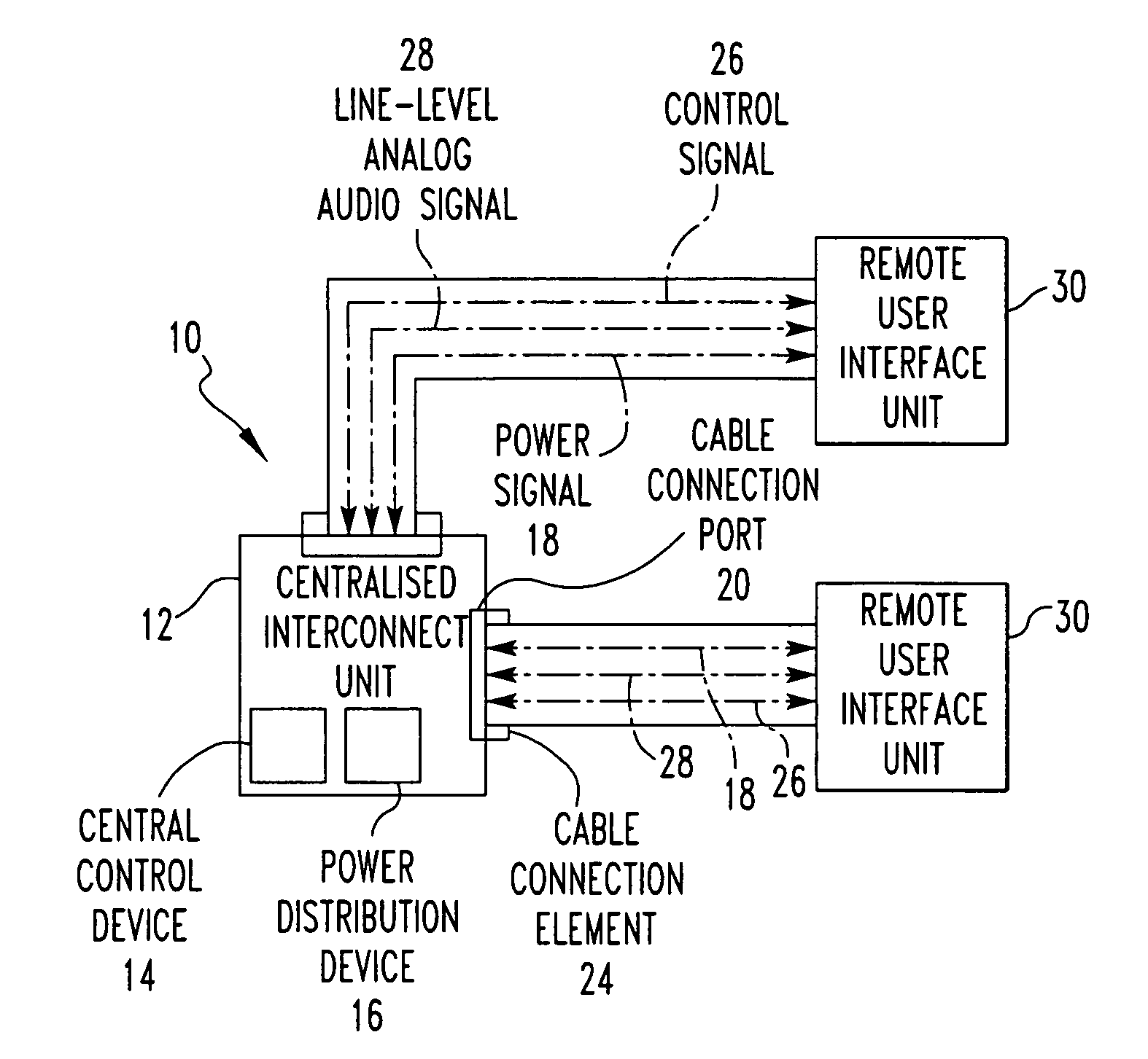
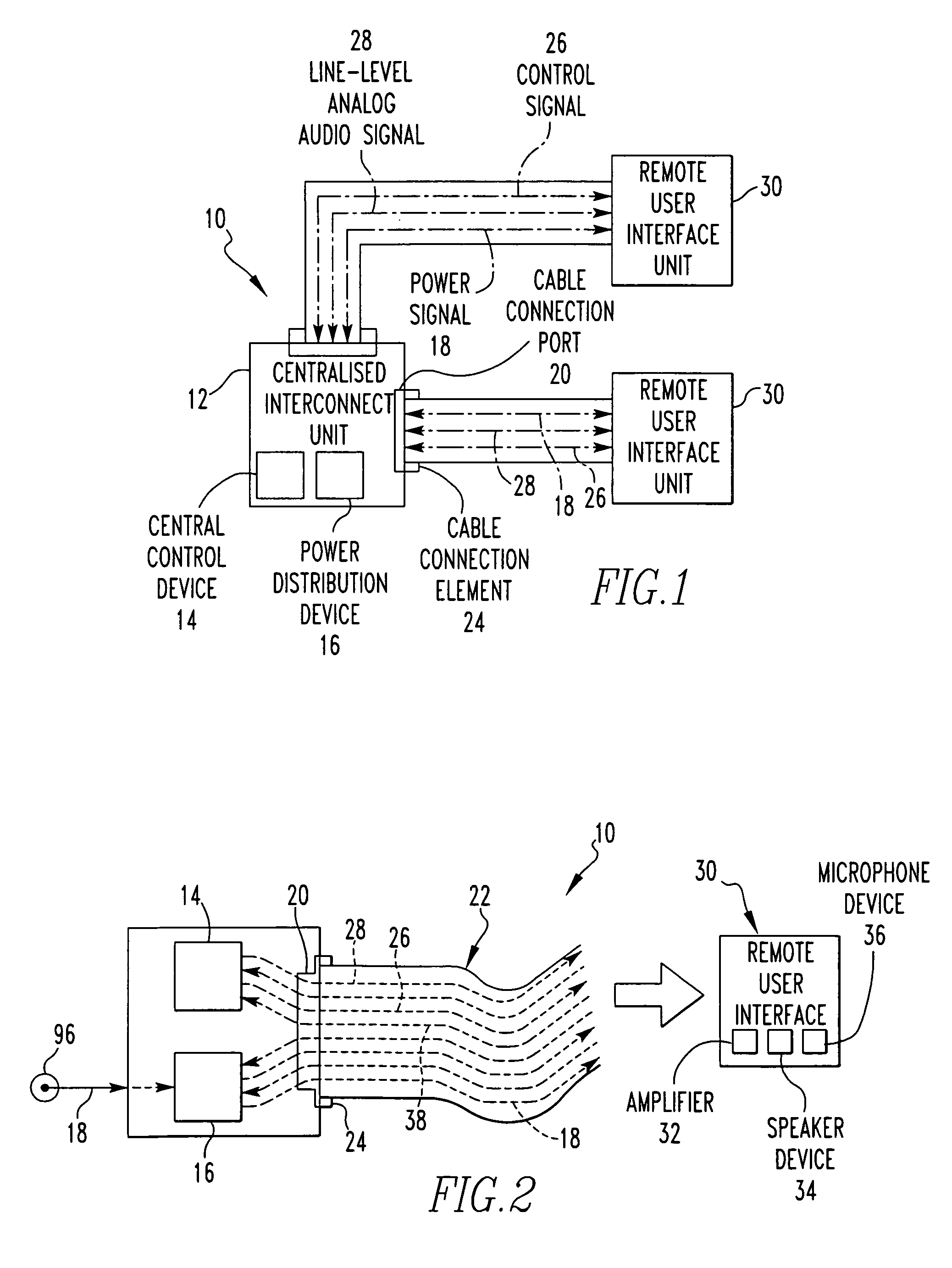
[0035]The present invention is a distributed intercom system 10, as illustrated in various embodiments in FIGS. 1, 2 and 5-9. Additionally, preferred and non-limiting embodiments of the various components and subcomponents of t...


PUM


Abstract

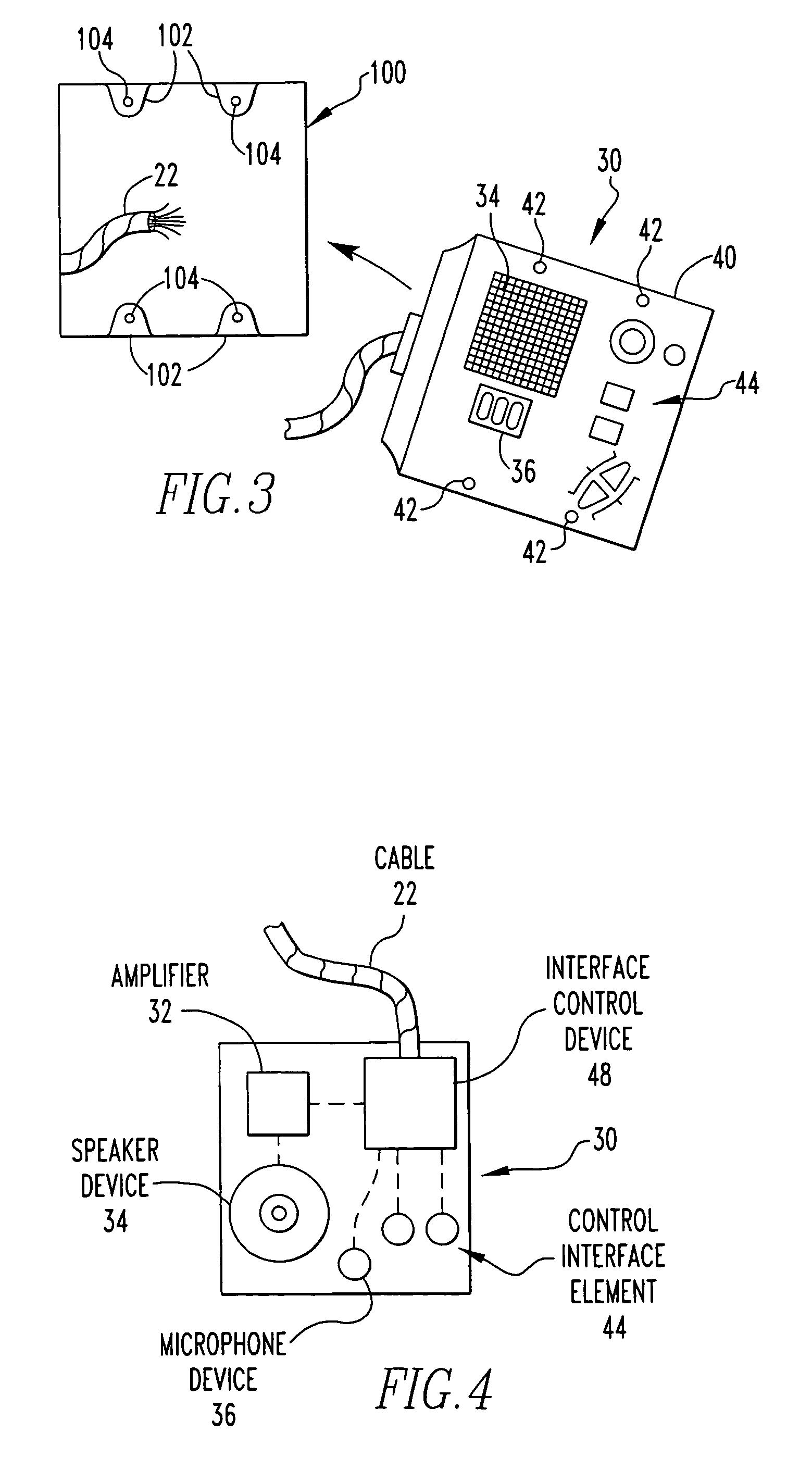
A distributed intercom system including a centralized interconnection unit with a central control device for receiving, processing and transmitting signals, a power distribution device for transmitting a power signal for distribution and at least one cable connection port for receiving a cable connection therein. The system includes a cable with a cable connection element for connection to the cable connection port, and the cable transmits a control signal, a line-level, analog audio signal and the power signal. One or more remote user interface units are connected to and in communication with the centralized interconnection unit through the cable, and the remote user interface unit includes an amplifier, a speaker device and a microphone device. At least one component of the remote user interface unit is powered by the power signal transmitted by the power distribution device.

Description

CROSS REFERENCE TO RELATED APPLICATIONS[0001]This application claims the benefit of priority from U.S. Provisional Patent Application No. 60 / 666,380, filed Mar. 30, 2005, which is incorporated herein by reference in its entirety.BACKGROUND OF THE INVENTION[0002]1. Field of the Invention[0003]The present invention relates generally to intercommunication and audio distribution systems and apparatus for use in both residential and commercial settings and, in particular, to an intercom system that provides distributed line-level, analog audio signals for remote amplification, control functionality at each remote unit, as well as communication between a central control unit, the remote units and other external audio and / or visual systems.[0004]2. Description of the Related Art[0005]Presently, intercom systems are used throughout the world in both residential and commercial settings. These systems allow persons to communicate in remote areas throughout a setting or building using an inter...

Claims


Application Information

Patent Timeline
Patent Type & Authority Patents(United States)
IPC IPC(8): H04M1/60H04M9/00
CPCH04M11/025
Inventor TARKOFF, DANIEL M.FLETCHER, DONALD R.HAHNE, AMY J.BRUGGEMEIER, WILLIAM E.MILLER, MATTHEW T.
Owner LEGRAND HOME SYST
Learn More