Modular Vehicular Diagnostic Tool

a diagnostic tool and module technology, applied in the direction of instruments, structural/machine measurement, transportation and packaging, etc., can solve the problems of not being able to upgrade the scan tool, not being able to permit the use of the scan tool, and costing the technician and customer

Active Publication Date: 2010-08-12
OPUS IVS INC
View PDF27 Cites 41 Cited by
  • Summary
  • Abstract
  • Description
  • Claims
  • Application Information

AI Technical Summary

Benefits of technology

[0015]It is still yet a further objective of the invention to provide an intelligent cable to be used in conjunction with the modules. The intelligent cable ha

Problems solved by technology

This is very costly to the technician and customer.
In the case where a vehicle requires a new hardware interface these scan to

Method used


Image

  • Modular Vehicular Diagnostic Tool
  • Modular Vehicular Diagnostic Tool
  • Modular Vehicular Diagnostic Tool

Examples


first embodiment

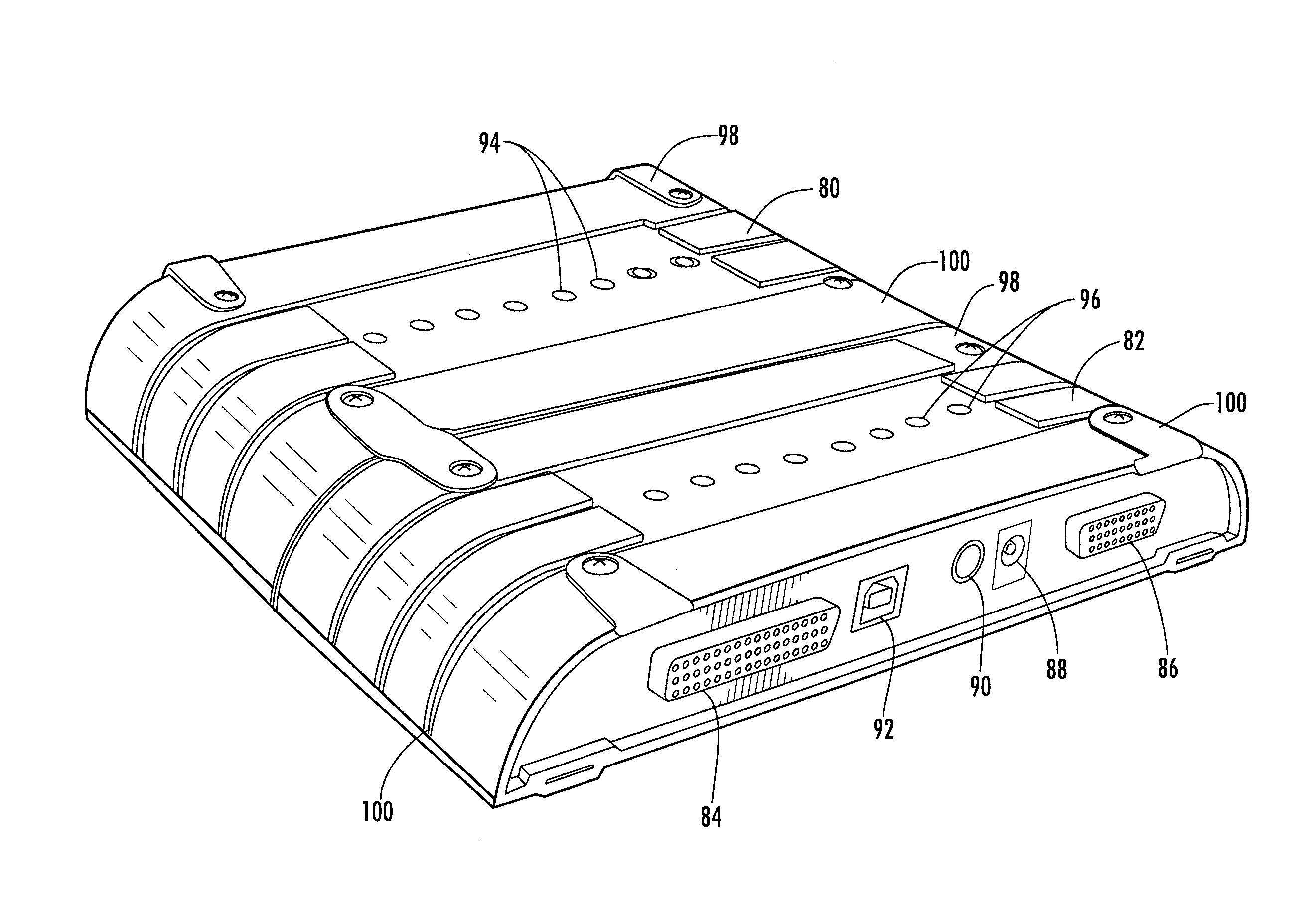
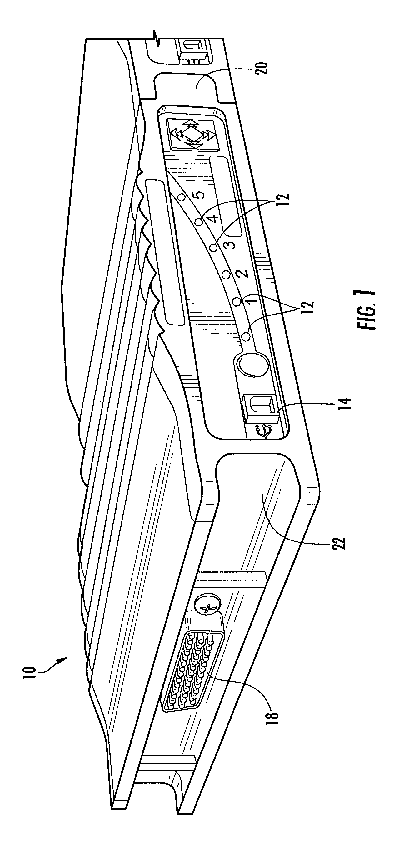
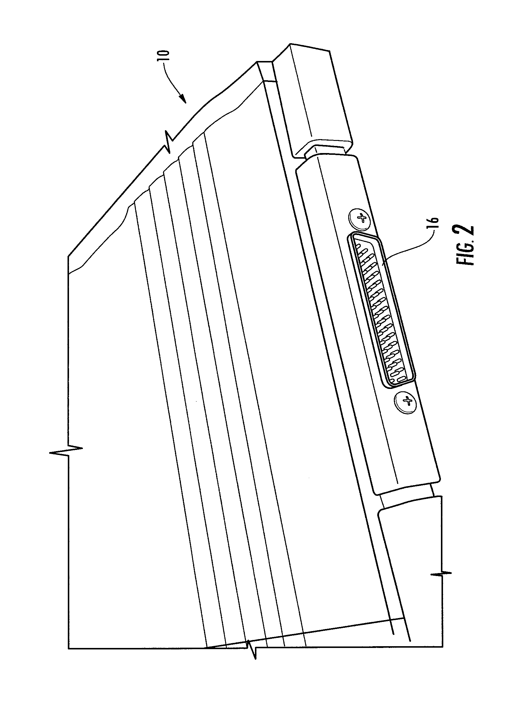
[0035]Referring now to FIGS. 1-17 the present invention will now be described. a module, diagnostic or re-flashing tool 10 is illustrated in FIGS. 1-3. In FIG. 1 a front portion of the tool includes a plurality of light emitting diodes (LED) 12 which can indicate the status of specific conditions of the module or of a vehicle. A USB connector 14 is also positioned on the front of the tool 10. The USB connector enables the tool to communicate with other devices such as lap top computers and other diagnostic tools or modules. This data can be utilized to analyze one or more problems with the vehicle. Data can also be uploaded into the vehicle utilizing the laptop computer. The LEDs can be used to indicate the condition of the upload of data or the module. These modules 10 are provided with a multi-pin connector 16 (FIG. 2) which is electrically connected to a multi-pin receptacle 18 (FIG. 1). The connection of 16 and 18 enable the tools or modules which are connected to each other to ...

second embodiment

[0038]FIG. 4 illustrates the present invention. A module 30 is connected to a module 32 in a manner similar to how modules 24 and 26 are connected to each other. Module 30 can be a basic module and module 32 can be an add-on module. Pin connector 34 enables the individual modules to be connected to each other. A port 36 in the form of a 16 pin connector provides a connection for a cable to connect the modules to a vehicle. For example, a cable can be connected to port 36 and the OBD output port on a vehicle. The modules can include an input / out board. The input / outboard being constructed and arranged to be connected to devices such as thermocouples, analogue inputs, digital inputs / outputs.

[0039]Connection 38 is an input for power. This input can be connected to a low voltage source and provides power to the modules and / or the vehicle. Some diagnostic tests and software upgrades require power to be supplied to the vehicle. Connection 40 is an output for power. This can be connected t...


PUM


Abstract

A vehicle computer interface and software upgrade tool is in the form of a module. A base module contains basic vehicle interface, information and software. Additional modules can be connected to the base module or similar modules to provide a user or technician with the latest interface and software upgrades for vehicles, new vehicle data and new reprogramming features for existing vehicles. This is an expandable system which enables a user of technician to only purchase a relatively small module or component that contains the new interface or information rather than having to repurchase an entire new scan tool or vehicle analyzer. The modules are readily connectable to a vehicle's data port, commonly known as an OBD II connector or port. The modules also include additional connection ports for power in, power out, USB and/or pin connectors which provide for the export of data and other connectors. These modules can also be used in conjunction with an intelligent cable. The intelligent cable has a small computer embedded within the cable to enable sensitive electronic components to be used without cable transmission losses or electrical disturbances.

Description

CROSS REFERENCE TO RELATED APPLICATIONS[0001]This application is a continuation-in-part of U.S. patent application Ser. No. 12 / 341,850, filed Dec. 22, 2008 and entitled, “USER CONFIGURED DISPLAY SYSTEM FOR MOTOR VEHICLE”, which is a continuation-in-part of U.S. patent application Ser. No. 12 / 046,072, filed Mar. 11, 2008 and entitled, “DATA ACQUISITION AND DISPLAY SYSTEM FOR MOTOR VEHICLES”, which is a continuation-in-part of U.S. patent application Ser. No. 11 / 836,672, filed Aug. 9, 2007 and entitled, “DATA ACQUISITION AND DISPLAY SYSTEM FOR MOTOR VEHICLE”, the contents of these applications are hereby incorporated in their entirety.FIELD OF THE INVENTION[0002]The present invention generally relates to an electronic diagnostic device for use in a motor vehicle, and more particularly to an electronic diagnostic device which can be used in conjunction with a vehicle's computer to test and program vehicles. This device can be physically and electronically connected to a similar device ...

Claims


Application Information

Patent Timeline
IPC IPC(8): G06F19/00
CPCG07C2205/02B60R16/0232
Inventor DREW, MICHAELHERRON, BRIAN
Owner OPUS IVS INC
Why Eureka
Try Eureka