Transceiver and interface for IC package

a technology of ic packages and transceivers, applied in the direction of coupling device connections, semiconductor/solid-state device testing/measurement, instruments, etc., can solve the problems of increasing the bit error rate, limiting the placement of components on the pcb, and difficult to transmit data to and from ic packages over copper connections

Active Publication Date: 2013-01-03
SAMTEC
View PDF1 Cites 36 Cited by
  • Summary
  • Abstract
  • Description
  • Claims
  • Application Information

AI Technical Summary

Benefits of technology

[0025]The above and other features, elements, characteristics and advantages of the present invention will become more apparent from the following detailed description of preferred embodiments of the present invention with reference to the attached drawings.

Problems solved by technology

Increased bandwidth demands make it difficult to transmit data to and from IC packages over copper connections, including the traces 502 shown in FIG. 18.
This approach as shown in FIG. 18 with a lengthy path has many drawbacks, including:1. Requiring more power to amplify or recover the data signals, which increases the bit error rate and which creates some limitations in the placements of components on the PCB, because data signals have to travel over lossy copper traces on a PCB.2. Increasing costs by increasing the number of components, including connectors, transceiver cages, housing, etc. and requiring a larger number of BGA connections between the IC package and the PCB because all the data signals have to be transmitted to and from the BGA of the IC package.
Known transceivers, including the conventional transceiver 500 shown in FIG. 18, cannot be adapted for connecting directly to an IC package because known transceivers are not small enough or have adequate mechanical retention.
Known transceivers require a large amount of space and consume hardware to mate or dock the optical engine.
Known transceivers cannot be adapted to both on-board and ball grid array (BGA) stepped-plane environments.
Size and geometry of known transceivers is limited by interference from low-speed signals and power signals being carried in the same transceiver as the high-speed signals.
That is, the IC package 514 must include, in addition to MPO 511, a converter that converts optical signals to electrical signals and that converts electrical signals to optical signals, which increases the size and cost of the IC package 514.
The IC package 524 includes an IC die 525 and a circuit board 526 with solder balls 526a. Because MPO 511 is an optical connector, MPO 511 is more expensive than a copper connector, and is sensitive to dust and other contamination.
In addition, the IC package 514 cannot be tested electrically during production because only a very expensive optical tester can be used.
Known transceivers, which typically include an optical engine and typically use pluggable connectors, are not designed to be directly connected to an IC package.
Known transceivers are not small enough or have adequate mechanical retention.
Known transceivers require a large amount of space and require hardware to mate or dock the optical engine.
Known transceivers cannot be adapted to both on-board and ball grid array (BGA) stepped-plane environments.
Typical transceivers have a single electrical connector that transmits all of the high speed signals, the low speed signals, and the power and ground signals, which limits miniaturization of the transceiver.

Method used


Image

  • Transceiver and interface for IC package
  • Transceiver and interface for IC package
  • Transceiver and interface for IC package

Examples


Embodiment Construction

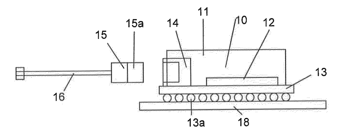
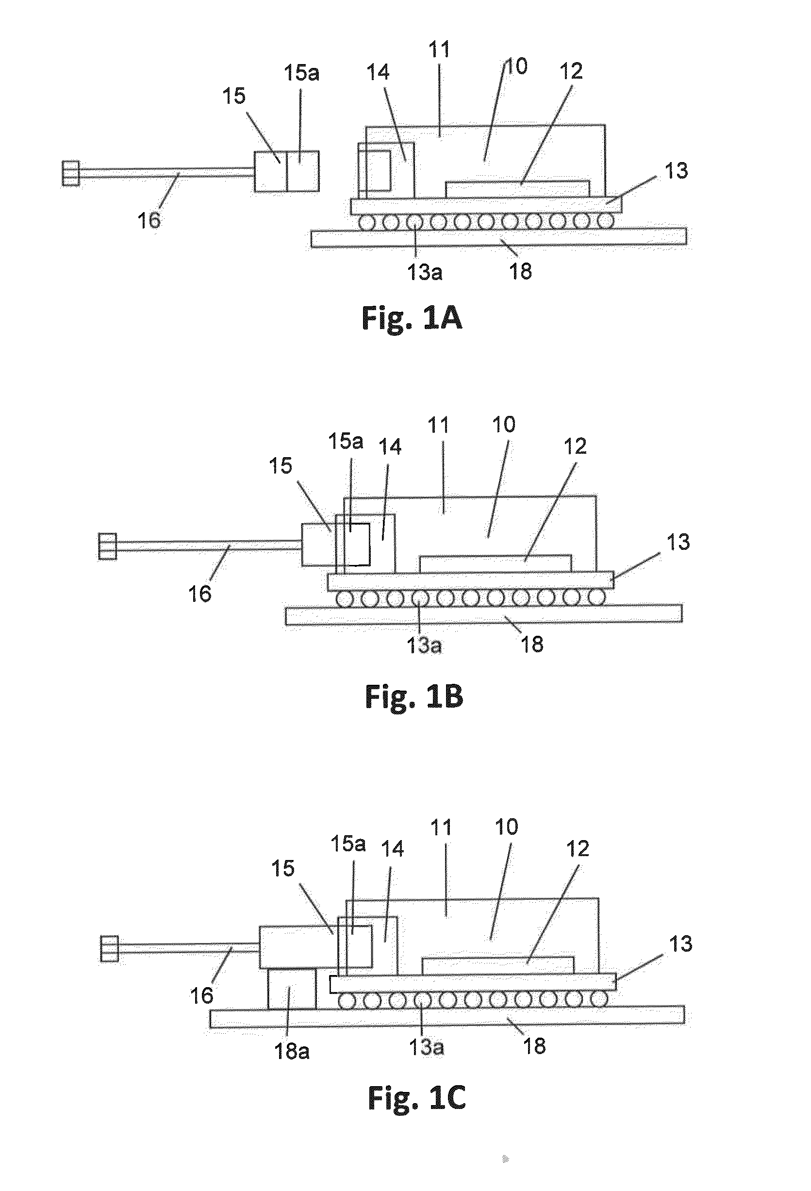
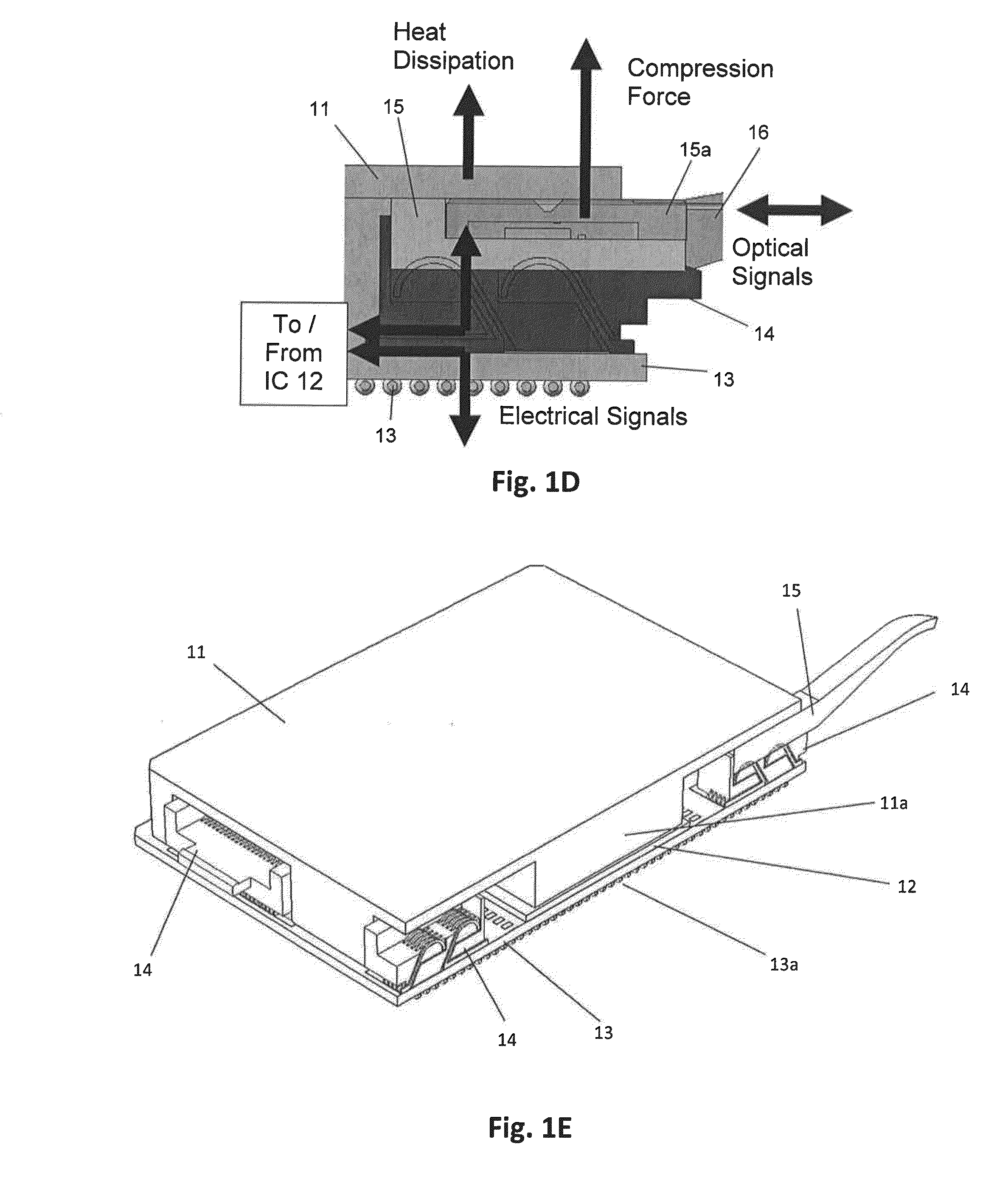
[0059]FIGS. 1A-1E are conceptual drawings of the IC package 10 and the transceiver 15 according to a preferred embodiment of the present invention. FIG. 1A shows an IC package 10 and a transceiver 15 before being mated together, while FIG. 1B shows the IC package 10 and the transceiver 15 mated together. The IC package 10 includes an IC die 12 and an enclosure (e.g., lid 11 and circuit board 13) for protecting the IC die 12 and electrical contacts (e.g., solder balls 13a) for transmitting electrical signals in a larger overall system. The transceiver 15 includes an optical engine 15a and is connected to cable 16. The cable 16 preferably includes a plurality of fiber optic cables. It is also possible for the cable 16 to include, in addition to fiber optic cables, one or more copper cables. The optical engine 15a converts optical signals into electrical signals and electrical signals into electrical signals. The optical engine 15a is preferably a pluggable optical engine that includes...


PUM


Abstract

An interconnect system includes a first circuit board, first and second connectors connected to the first circuit board, and a transceiver including an optical engine and arranged to receive and transmit electrical and optical signals through a cable, to convert optical signals received from the cable into electrical signals, and to convert electrical signals received from the first connector into optical signals to be transmitted through the cable. The transceiver is arranged to mate with the first and second connectors so that at least some converted electrical signals are transmitted to the first connector and so that at least some electrical signals received from the cable are transmitted to the second connector.

Description

BACKGROUND OF THE INVENTION[0001]1. Field of the Invention[0002]The present invention relates to transceivers and IC packages. More specifically, the present invention relates to transceivers that can be directly plugged into an IC package.[0003]2. Description of the Related Art[0004]FIG. 18 shows a conventional transceiver 500 and a conventional integrated circuit (IC) package 504. The transceiver 500 is connected to a socket 501 on a printed circuit board (PCB) 503. The IC package 504 is connected to the PCB 503 through solder balls 504a. The IC package 504 is a ball grid array (BGA). The IC package 504 is connected to the socket 501 by traces 502 located on or in the PCB 503. The transceiver 500 includes an optical engine that provides optical-to-electrical and electrical-to-optical conversion. That is, the electrical signals received from the IC package 504 are converted to optical signals that are transmitted through the optical fiber cable 500a, and all optical signals receive...

Claims


Application Information

Patent Timeline
Patent Type & Authority Applications(United States)
IPC IPC(8): G02B6/12
CPCG02B6/4232G02B6/4246H04B10/40H04B1/3833G02B6/4261H01L2224/48091H01L2224/49175H01L2924/00014G02B6/43H01L22/00G02B6/46H04B10/25891H04B10/27G02B6/4249G02B6/4269G02B6/428G02B6/4284G02B6/4278G02B6/4292H04B10/803G02B6/4279G02B6/4293H05K7/20418H01R13/639H01R12/716H04B10/801
Inventor ZBINDEN, ERICMUSSER, RANDALLVERDIELL, JEAN-MARC ANDREMONGOLD, JOHNVICICH, BRIANGUETIG, KEITH
Owner SAMTEC
Why Eureka
Try Eureka