Transluminal sheath hub

a technology of transluminal sheath and hub, which is applied in the field of medical devices for transluminal accessing body lumens and cavities, can solve the problems of not easy or tedious instrumentation introduction, the sheath hub is not secure, and the sheath hub is available today without secure connection to the dilator hub

Inactive Publication Date: 2007-01-25
ONSET MEDICAL CORP
View PDF24 Cites 47 Cited by
  • Summary
  • Abstract
  • Description
  • Claims
  • Application Information

AI Technical Summary

Benefits of technology

[0013] For purposes of summarizing the invention, certain aspects, advantages and novel features of the invention are described herein. It is to be understood that not necessarily all such advantages may be achieved in accordance with any particular embodiment of the invention. Thus, for example, those skilled in the art will recognize that the invention may be embodied or carried out in a manner that achieves one advantage or group of advantages as taught herein without necessarily achieving other advantages as may be taught or suggested herein. These and other objects and advantages of the present invention will be more apparent from the following description taken in conjunction with the accompanying drawings.

Problems solved by technology

One of the issues that arise during ureteroscopy is the need to grasp the proximal end of the sheath.
Another issue that arises during ureteroscopy is the attachment between the sheath and a dilator or obturator inserted therethrough.
Furthermore, the hub needs to be able to guide instrumentation inserted into the sheath so that such introduction of instrumentation is not difficult or tedious.
Sheath hubs available today do not have secure connections to the dilator hub and are often too large for easy grasping.

Method used


Image

  • Transluminal sheath hub
  • Transluminal sheath hub
  • Transluminal sheath hub

Examples


Embodiment Construction

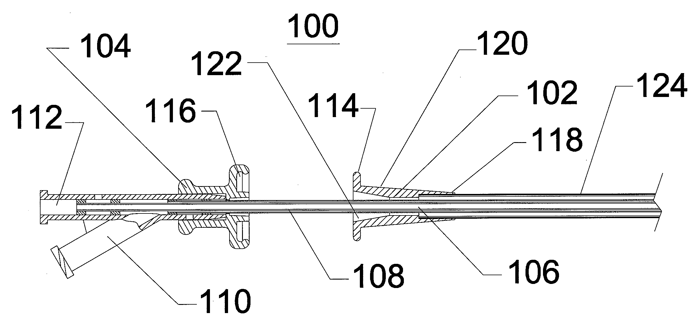
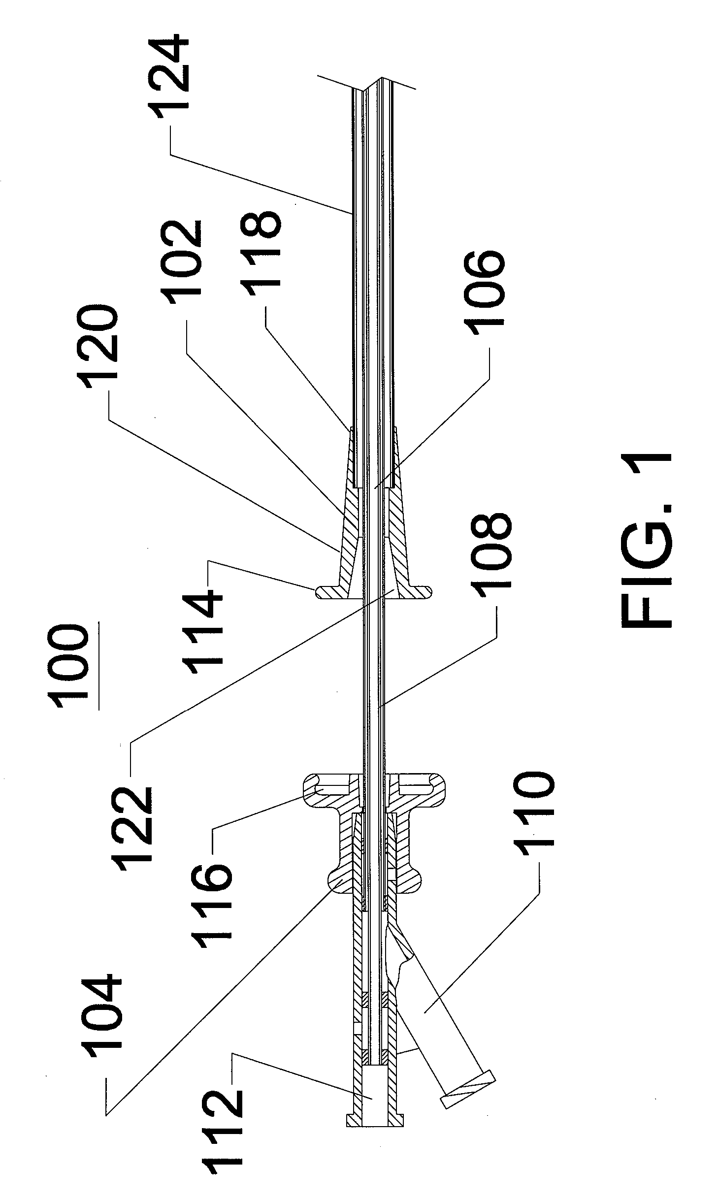
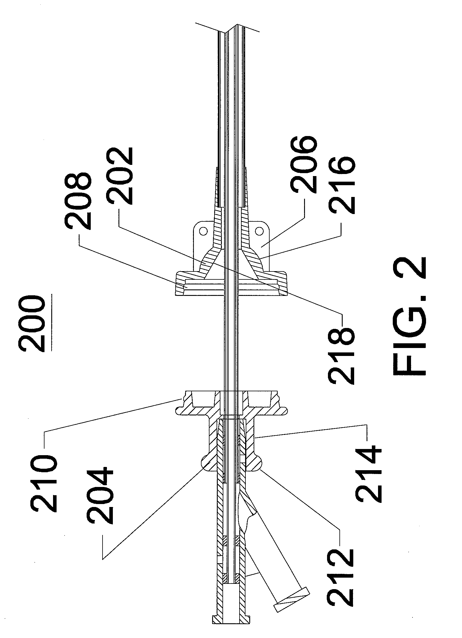
[0031] In the embodiments described below reference will be made which is to a “catheter” or a “sheath”, which can comprise a generally axially elongate hollow tubular structure having a proximal end and a distal end. The axially elongate structure can include a longitudinal axis and an internal through lumen that extends from the proximal end to the distal end for the passage of instruments, implants, fluids, tissue, or other materials. While in many of the embodiments described herein the tubular structure has a generally round or circular cross-section, in modified embodiments, the tubular structure can have a non-round (e.g., square) or non-circular (e.g., oval) cross-section. The axially elongate hollow tubular structure can be generally flexible and capable of bending, to a greater or lesser degree, through one or more arcs in one or more directions perpendicular to the main longitudinal axis. As is commonly used in the art of medical devices, the proximal end of the device is...


PUM


Abstract

Disclosed is a hub for a transluminal sheath. The hub provides a handle for grasping the sheath, provides connections for fluid inlet and outlet lines, and provides for attaching mechanisms between the sheath and a dilator. The hub can be used on a non-radially expandable sheath, or it can be used on a sheath having a radially expandable configuration. In an exemplary application, the hub is fitted to a sheath, which provides access for a diagnostic or therapeutic procedure such as ureteroscopy or stone removal.

Description

PRIORITY INFORMATION [0001] This application claims the priority benefit under 35 U.S.C. § 119(e) of Provisional Application 60 / 695,790, filed Jun. 29, 2005, the entirety of which is hereby incorporated by reference herein.BACKGROUND OF THE INVENTION [0002] 1. Field of the Invention [0003] The invention relates to medical devices and, more particularly, to medical devices for transluminally accessing body lumens and cavities. [0004] 2. Description of the Related Art [0005] A wide variety of diagnostic or therapeutic procedures involves the introduction of a device through a natural access pathway such as a body lumen or cavity. A general objective of such access systems, which have been developed for this purpose, is to minimize the cross-sectional area of the access lumen, while maximizing the available space for the diagnostic or therapeutic instrumentation. These procedures are especially suited for the urinary tract of the human or other mammal. The urinary tract is relatively s...

Claims


Application Information

Patent Timeline
Patent Type & Authority Applications(United States)
IPC IPC(8): A61F2/00
CPCA61M25/0097
Inventor LENKER, JAYNANCE, EDWARD J.BISHOP, JOSEPHKICK, GEORGE F.
Owner ONSET MEDICAL CORP
Why Eureka
Try Eureka