Bottle filler

a filler and bottle technology, applied in the field of bottle filling devices, can solve the problems of beer adversely affecting flavor and shelf life, too much carbonation loss from foaming leaving the beer flat, unsatisfactory yeast sediment in the bottom of each bottle, etc., and achieves the effects of reducing or eliminating sharp bends and valves, easy sanitization, and intuitive us

Active Publication Date: 2007-02-01
BLICHMANN JOHN RICHARD
View PDF5 Cites 18 Cited by
  • Summary
  • Abstract
  • Description
  • Claims
  • Application Information

AI Technical Summary

Problems solved by technology

The alternate to filling from a keg is natural carbonation in the bottle; but this leaves undesirable yeast sediment in the bottom of each bottle.
Simply pouring the beer into a bottle from a tap is possible, but too much carbonation is lost from foaming leaving the beer flat.
In addition, the presence of oxygen (O2) in the bottle during transfer causes staling of the beer adversely affecting the flavor and shelf life.
The typical process to fill a bottle utilizing a homebrew type counter-pressure bottle filler (CPBF) requires a very cumbersome process of turning several valves in a prescribed sequence in order to purge the bottle of air (O2), pressurize the bottle to the same pressure as the keg (to reduce foaming and carbonation loss), turn on the beer flow valve, gradually open the CO2 relief valve to allow beer to flow, turn the beer valve off at the correct fill level, relieve the CO2 pressure in the bottle, and remove the filler assembly, and lastly cap the bottle.
If any operations are missed or done in the incorrect order, the bottle could be too foamy (lost carbonation), not at the correct fill level, inadequately purged of air or accidentally sprayed out of the bottle leaving an undesirable mess.
This sudden pressure loss is due to the sharp turns from numerous fittings and elbows, in addition to the throttling nature of valves that would otherwise cause excessive foaming if the bottle was not pressurized prior to filling.

Method used


Image

  • Bottle filler
  • Bottle filler
  • Bottle filler

Examples


Embodiment Construction

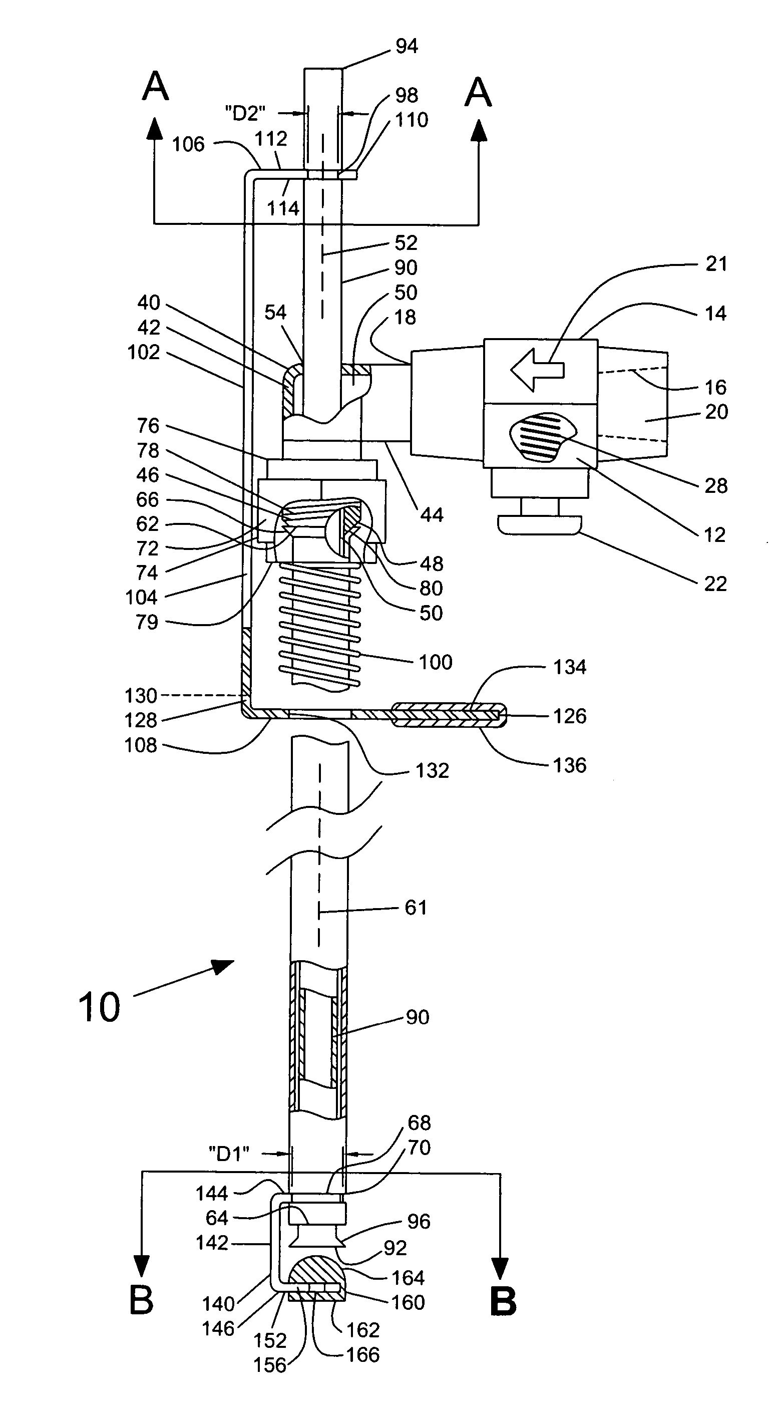
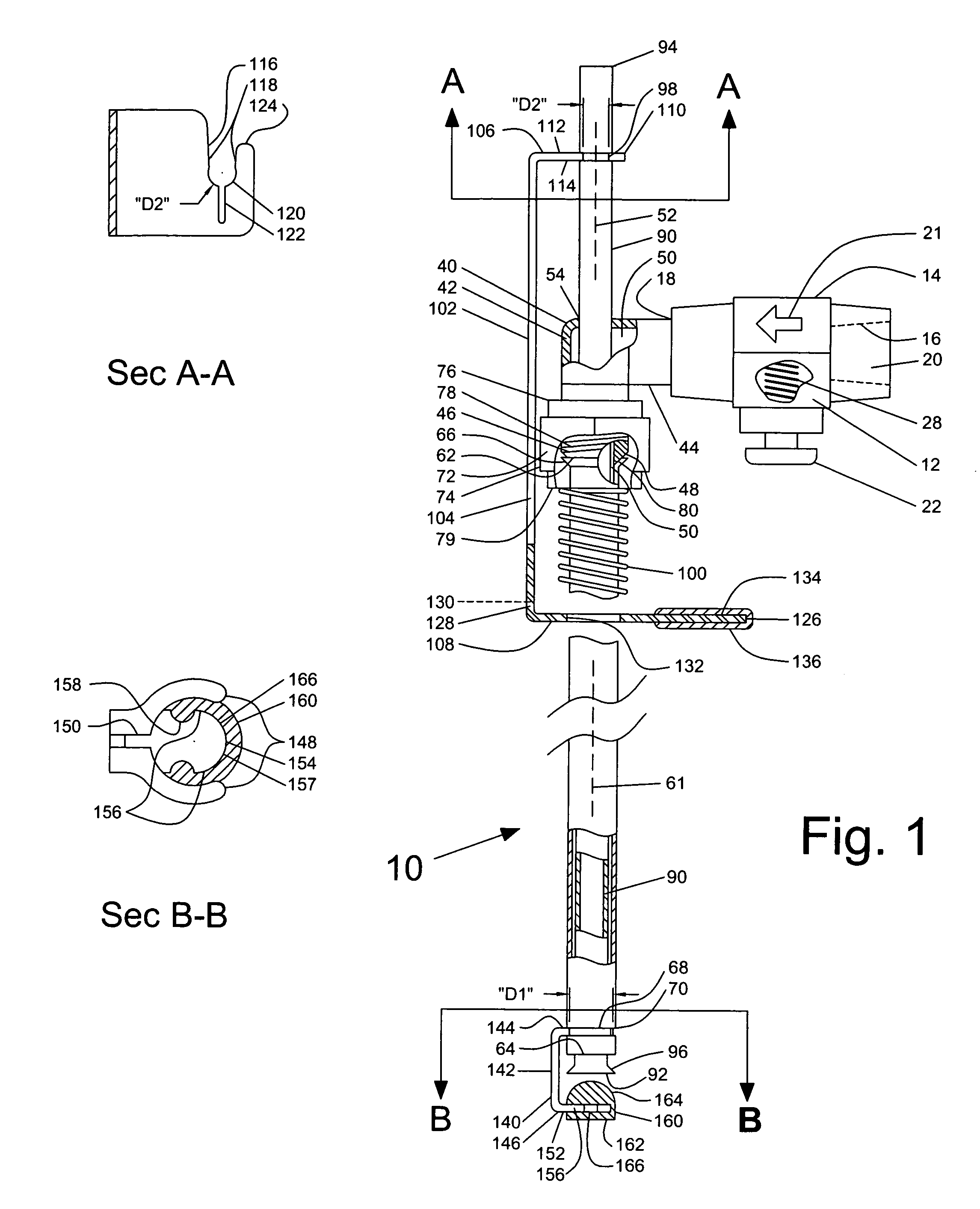
[0012] Referring to prior art FIG. 3, prior art numerical appear as primed numbers (′) a common prior art counter-pressure bottle filler (CPBF) 10′ is shown. CPBF 10′ is comprised of commercially available valves, fittings and tubing. Beer valve 140′ is connected to the liquid out 2′ on a keg 1′. CO2 valve 12′ is connected to CO2 tank 3′ which is also connects CO2 to the keg 1′. A bleed valve 6′ is connected to a beer stem 7′ and also to a CO2 bleed stem 8′. A stopper 9′ seals against bottle 5′.

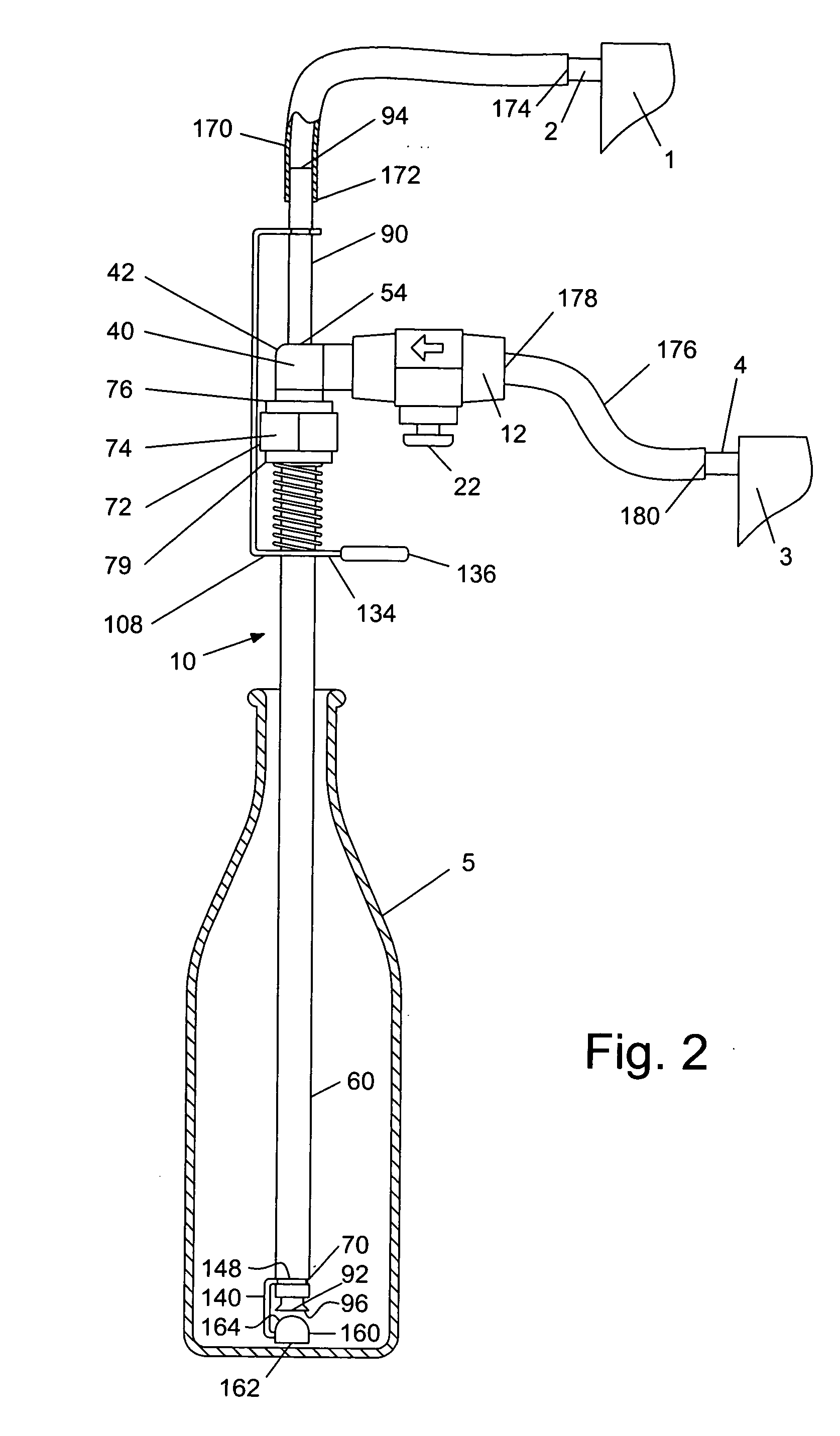
[0013] Referring to FIG. 1 having sections A-A and B-B and FIG. 2, the preferred embodiment is shown. A keg or container 1 of liquid to be drained having an outlet 2, a CO2 tank 3 having an outlet 4 and a bottle 5 are partially shown. A bottle filler assembly 10 is shown. The bottle filler assembly includes a CO2 valve 12 of conventional construction. In this application, the CO2 valve 12 is made of a brass material, but as an alternative could be stainless steel or copper or another materia...


PUM

PropertyMeasurementUnit
90 degree angleaaaaaaaaaa
angleaaaaaaaaaa
angleaaaaaaaaaa

Abstract

An improved bottle filler assembly for filling bottles from kegged carbonated or non carbonated beverages without carbonation loss or oxidation that is intuitive to use, sanitize, and keep free of bacteria. In the preferred embodiment, a long hose gradually reduces the pressure of the beverage on the way to the filler. Two tubes are placed inside each other forming an annulus where CO2 can be forced to the bottom of the bottle via a CO2 valve thereby purging the bottle of air (O2). A valve seat placed on the bottom of the tubes allows the beverage to flow into the bottle from the bottom by depressing a trigger.

Description

FIELD OF THE INVENTION [0001] This invention relates generally to bottle filling devices, specifically to bottle filling devices for home made beer and other liquid carbonated beverages. BACKGROUND Discussion of Prior Art [0002] It is well known in the home made beer (homebrew) market to utilize a specialized filler to transfer carbonated beer from a pressurized keg into a bottle for portability, gifts, entering into competitions and the like. The alternate to filling from a keg is natural carbonation in the bottle; but this leaves undesirable yeast sediment in the bottom of each bottle. Simply pouring the beer into a bottle from a tap is possible, but too much carbonation is lost from foaming leaving the beer flat. In addition, the presence of oxygen (O2) in the bottle during transfer causes staling of the beer adversely affecting the flavor and shelf life. The common solution to this is a device called a counter-pressure bottle filler (CPBF), which is very common in both the comme...

Claims


Application Information

Patent Timeline
Patent Type & Authority Applications(United States)
IPC IPC(8): B67B3/00
CPCB67C3/04B67C3/26B67C3/222
Inventor BLICHMANN, JOHN RICHARD
Owner BLICHMANN JOHN RICHARD
Why Eureka
Try Eureka