
System comprising magnetically actuated motion control device

a motion control device and magnetic actuator technology, applied in the direction of shock absorbers, chairs, transportation and packaging, etc., can solve the problems of not being particularly easy to manufacture and assemble, and complicating manufacture and assembly

Inactive Publication Date: 2007-02-01
LORD CORP
View PDF42 Cites 57 Cited by
  • Summary
  • Abstract
  • Description
  • Claims
  • Application Information

AI Technical Summary

Benefits of technology

[0007] According to one aspect of the invention, a magnetically actuated motion control device is provided. The magnetically actuated motion control device includes a housing, and movable member and a magnetic field generator located on either the housing or

Problems solved by technology

In particular, such dampers typically require a dynamic seal and a compliant containment member which are not particularly easy to manufacture and assemble.
Further, the fluid type dampers can have significant “off-state” forces which can further complicate manufacture and assembly.

Method used


Image

  • System comprising magnetically actuated motion control device
  • System comprising magnetically actuated motion control device
  • System comprising magnetically actuated motion control device

Examples


first embodiment

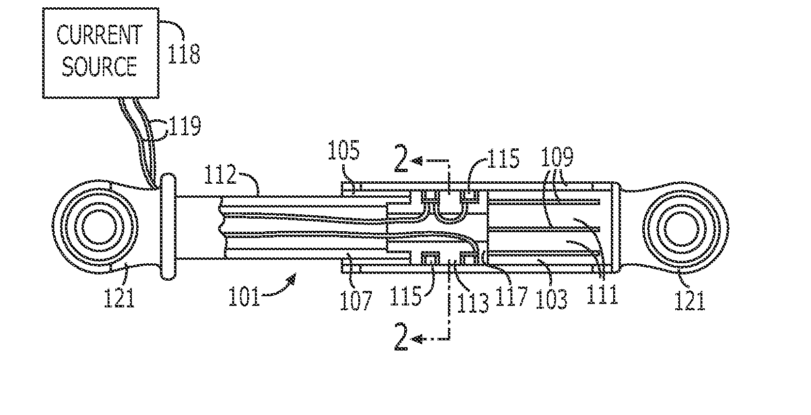
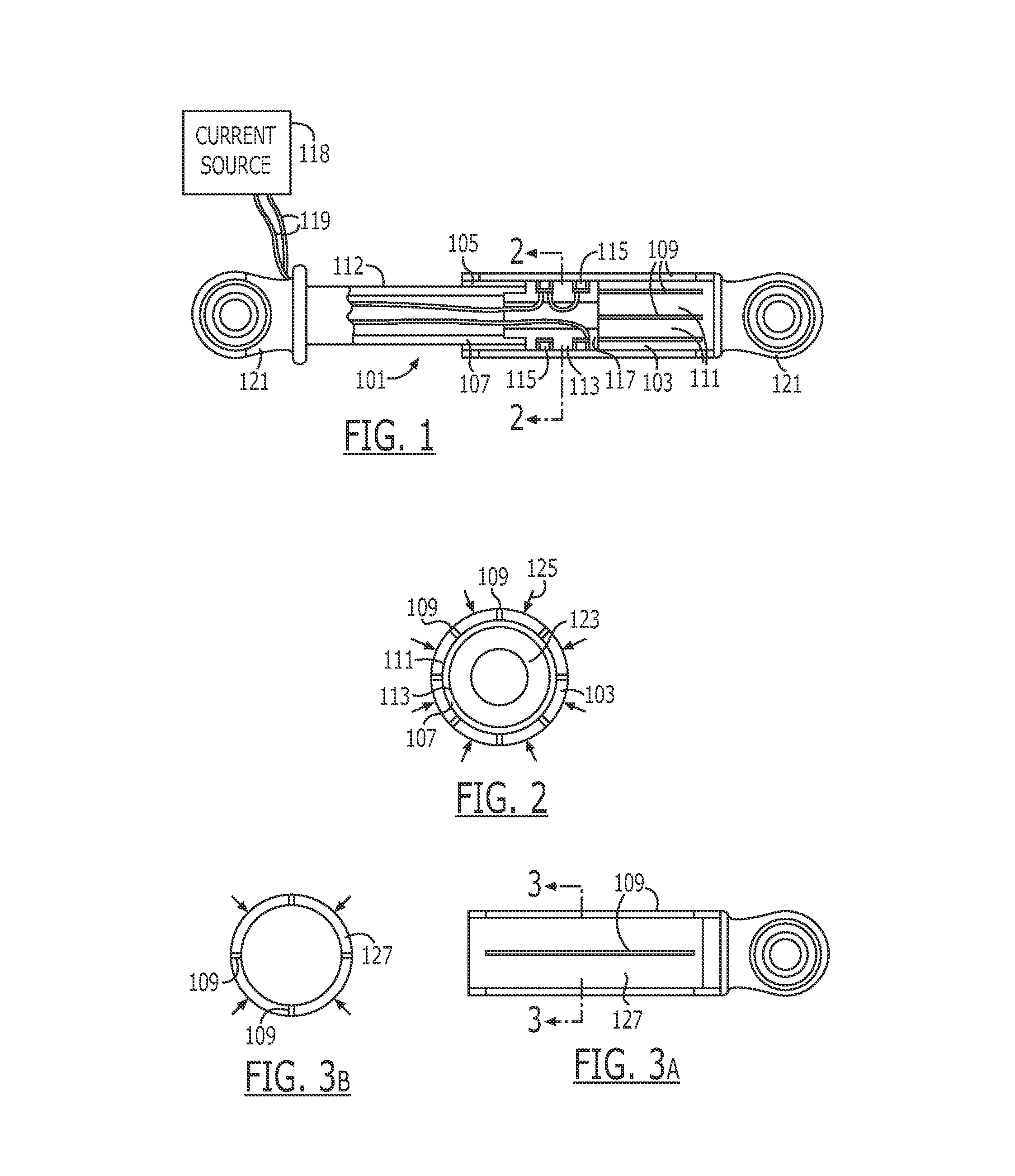
[0090] Turning to the drawings, a first exemplary embodiment of a magnetically actuated motion control device according to the present invention is shown in FIGS. 1 and 2. The first embodiment motion control device is a damper 101 and includes a housing 103 defining a cavity 105 in which a piston 107 is located. The housing 103 includes a least one longitudinal slot 109 (five of eight such slots can be seen in FIG. 1). The housing shown in FIG. 1 includes a plurality of slots that pass through the housing wall to define flexible bands, tabs, or fingers 111. The slots 109 extend through the wall of the housing 103 and extend nearly the entire length of the housing 103. Although narrow slots are illustrated in the Figures, it should be understood that a suitable wide slot could also be provided in the housing.

[0091] The piston 107 includes a shaft 112 having a magnetically active portion 113 made up of at least one, and preferably two electromagnetic coils 115 set in a magnetically pe...

second embodiment

[0141] As explained earlier, the magnetic field generators, e.g., coils can be mounted to either the housing or the piston with the other of the housing or the piston being split into one or more flexible fingers. FIG. 41 shows a twenty-second embodiment of the present invention including a piston 413 having two magnetic coils 391 located within a core 414 and a slotted housing 415 in which the piston 413 is located. Like the embodiments discussed in reference to FIGS. 1 and 2, the housing 415 includes one or more longitudinal slots 417 that define one or more flexible fingers 419.

[0142] The piston 413 slides within the housing 415 on bearing assemblies 421, which are each located radially inward of the coils 391 and bear against the inner surface of the housing 415. Each bearing assembly includes an annular spring 425, which is located between an annular bearing 427 and one of the respective coils 391. The spring 425 biases the bearing 427 radially outward and away from the magneti...


PUM


Abstract

A system that includes a magnetically actuated motion control device comprising a housing defining a cavity and including a slot therethrough. A movable member is located within the cavity and is movable relative to the housing. A magnetic field generator located on either the housing or the movable member causes the housing to press against the movable member to develop a friction force.

Description

[0001] This application is a Continuation-In-Part of pending U.S. patent application Ser. No. 10 / 647,554, filed Aug. 25, 2003, which is a divisional of U.S. patent application Ser. No. 10 / 080293, filed Feb. 20, 2002 now U.S. Pat. No. 6,640,940, which was a divisional of pending U.S. patent application Ser. No. 09 / 537,365, filed Mar. 29, 2000 now U.S. Pat. No. 6,378,671.FEILD OF THE INVENTION [0002] The present invention relates to magnetically actuated motion control devices. In particular the present invention relates to magnetically actuated motion control devices that vary contact pressure between a first member and a second member in accordance with a generated magnetic field. BACKGROUN AND RELATED ART [0003] Magnetically actuated motion control devices such as magnetically controlled dampers or struts provide motion control, e.g., damping that is controlled by the magnitude of an applied magnetic field. Much of the work in the area of magnetically controlled dampers has focused...

Claims


Application Information

Patent Timeline
IPC IPC(8): F16F15/03
CPCA47C1/03F16F2222/06A47C31/003B60G17/0157B60N2/464B60N2/501B60N2/505B60N2/508B60N2/522B60N2/527B62D1/184B62D5/005B62D5/006D06F37/20F16F7/082F16F7/09F16F15/03A47C3/20B60N2/77F16F9/53
Inventor CARLSON, J. DAVIDWILDER, RICHARD
Owner LORD CORP
Learn More