Tensioning device of a traction mechanism drive

Active Publication Date: 2009-03-26
SCHAEFFLER TECH AG & CO KG
View PDF7 Cites 5 Cited by
  • Summary
  • Abstract
  • Description
  • Claims
  • Application Information

AI Technical Summary

Benefits of technology

[0014]Against this background, the invention is based on the object of specifying a tensioning device of the type mentioned at the outset that has, in a simple and overall space-

Problems solved by technology

However, as at least one of the radial planes in which the spring force of the torsional spring and the reaction force of the traction mechanism act on the tensioning lever is usually axially spaced apart from a central radial bearing plane of the pivot bearing or the plain bearing sleeve, there is inevitably obtained a resulting tilting moment about a tilt axis lying perpendicularly to the axis of rotation of the pivot bearing in the central bearing plane.
This tilting moment disadvantageously causes non-uniform, one-sided loading, i.e. loading acting axially at the end side in diagonal opposition, of the pivot bearing with high local compressive and edge loading of the plain bearing sleeve, leading to non-uniform wear of the plain bearing sleeve and accordingly to undesirable misalignment of the tensioning lever and also of the tensioning roller fastened thereto with respect to be traction mechanism.
Furthermore, it is difficult to adjust the radial spring force for exact compensation for the tilting mo

Method used


Image

  • Tensioning device of a traction mechanism drive
  • Tensioning device of a traction mechanism drive
  • Tensioning device of a traction mechanism drive

Examples


Example

DETAILED DESCRIPTION OF THE DRAWINGS

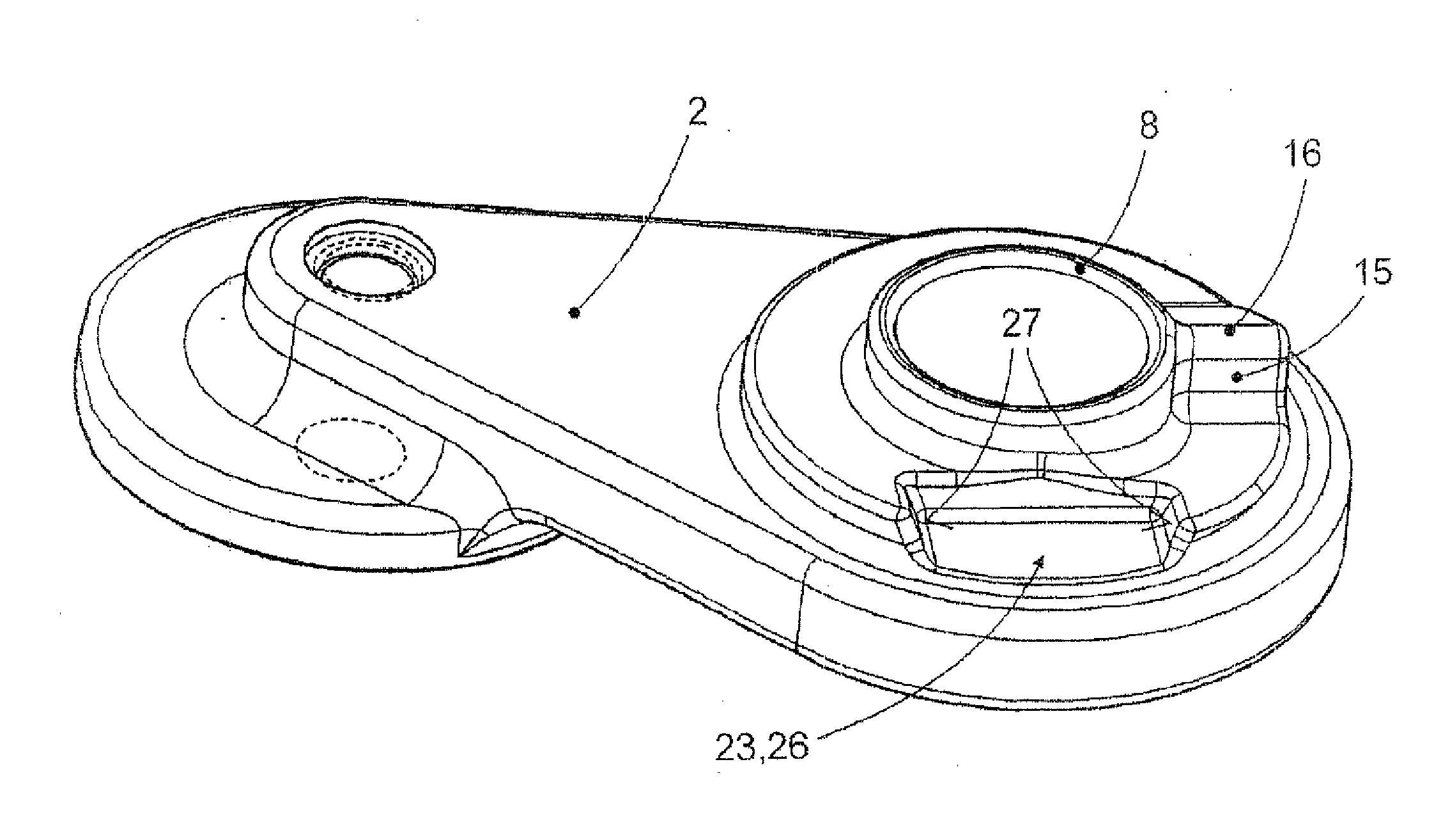
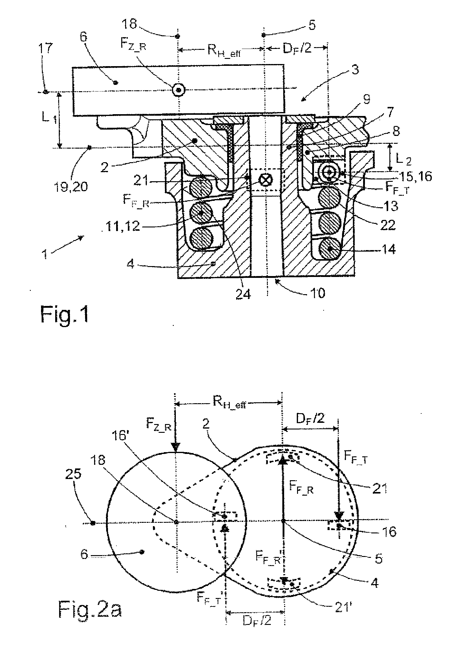
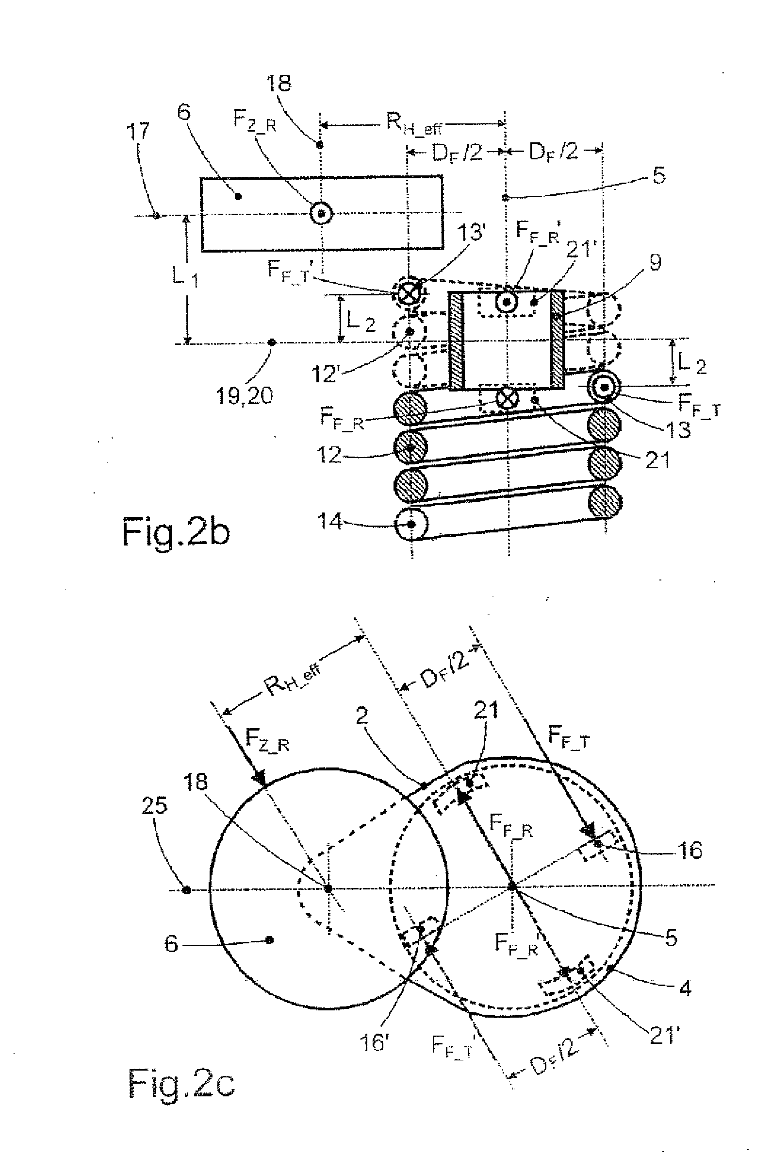
[0043]FIG. 1 is a longitudinal center section of a preferred embodiment of a tensioning device 1 according to the invention of a traction mechanism drive. In what is known as an offset or Z arrangement, a tensioning lever 2 is mounted on a base housing 4 so as to be able to rotate via a pivot bearing 3 and provided, radially spaced apart from the axis of rotation 5 of the pivot bearing 3, with a rotatable tensioning roller 6. The pivot bearing 3 is formed from a bearing journal 7, a bearing hub 8 and a plain bearing sleeve 9 arranged between the bearing journal 7 and the bearing hub 8, in the present case the bearing journal 7 being rigidly connected to the base housing 4 and the bearing hub 8 being part of the tensioning lever 2. The base housing 2 is provided, for fastening to another housing, for example a crankcase or a control housing of an internal combustion piston engine, with a central bore 10 through which, for example, a fastening screw...


PUM


Abstract

The invention relates to a tensioning device of a traction mechanism drive, having a tensioning lever mounted on a base housing and rotatable by a pivot bearing. A coil spring is arranged coaxially to the pivot bearing. The pivot bearing comprises a bearing journal, a bearing hub and at least one plain bearing sleeve which is arranged between the bearing journal and the bearing hub, and a central radial force application plane of the tensioning roller is axially spaced apart from a central radial bearing plane of the pivot bearing.

Description

FIELD OF THE INVENTION[0001]The invention relates to a tensioning device of a traction mechanism drive, having a tensioning lever which is mounted on a base housing so as to be able to rotate via a pivot bearing and, radially spaced apart from the axis of rotation of the pivot bearing, is provided with a rotatable tensioning roller, which tensioning lever can, by means of a torsional spring which is configured as a helical spring, is arranged coaxially with the pivot bearing and is connected at both spring ends at the housing side to the base housing and at the lever side to the tensioning lever, be acted on with a torsional moment about the axis of rotation of the pivot bearing, the pivot bearing comprising a bearing journal, a bearing hub and at least one plain bearing sleeve arranged between the bearing journal and the bearing hub, and a central radial force application plane of the tensioning roller being for the most part axially spaced apart from a central radial bearing plane...

Claims


Application Information

Patent Timeline
IPC IPC(8): F16H7/12
CPCF16H7/1218F16H2007/081F16H7/1281F16H7/08F16H7/12
Inventor SINGER, JOHANN
Owner SCHAEFFLER TECH AG & CO KG
Why Eureka
Try Eureka