Prophy angle

a technology of prophylaxis and angle, which is applied in the field of dental instruments, can solve the problems of affecting the prophylaxis effect,

Active Publication Date: 2007-02-01
AVID
View PDF75 Cites 13 Cited by
  • Summary
  • Abstract
  • Description
  • Claims
  • Application Information

AI Technical Summary

Problems solved by technology

One drawback of these current instruments is that they are often cumbersome to assemble and may contain a myriad of loosely fitting parts.
During use of the prophy angle, the housing may experience increased strain when in contact with the teeth of a patient, and cause the seams in the housing to separate and expose the inner components of the angle.
Such separation in the housing may result in a spacing apart or separation of the internal gears of the angle, potentially leading to failure of the device.
In addition to concerns regarding housing integrity, the drive shaft and driven gear of an angle may experience some displacement during use of the prophy angle.
As the angle is being used, the drive shaft may excessively move forward or backward due to an increase in the pressure placed on the rotating parts, and result either in an increased amount of force between the gear teeth of the drive shaft and the driven gear, or separation of engagement of the gear teeth of the shaft from those of the driven gear.
Subsequently, this displacement can also lead to a premature malfunction of the prophy angle prior to completing a dental procedure.
Furthermore, conventional prophy angles may have a significant amount of contact between surfaces of the housing, the drive shaft and the driven gear.
Such large, often flat surfaces can generate increasing amounts of friction as the prophy angle is used at higher rates of rotation.
The increased friction can prevent the prophy angle from reaching the desired rate of rotation, may cause enhanced wear and tear between the interacting components, and may generate greater heat, thus making the angle uncomfortable to use.

Method used


Image

  • Prophy angle
  • Prophy angle
  • Prophy angle

Examples


Embodiment Construction

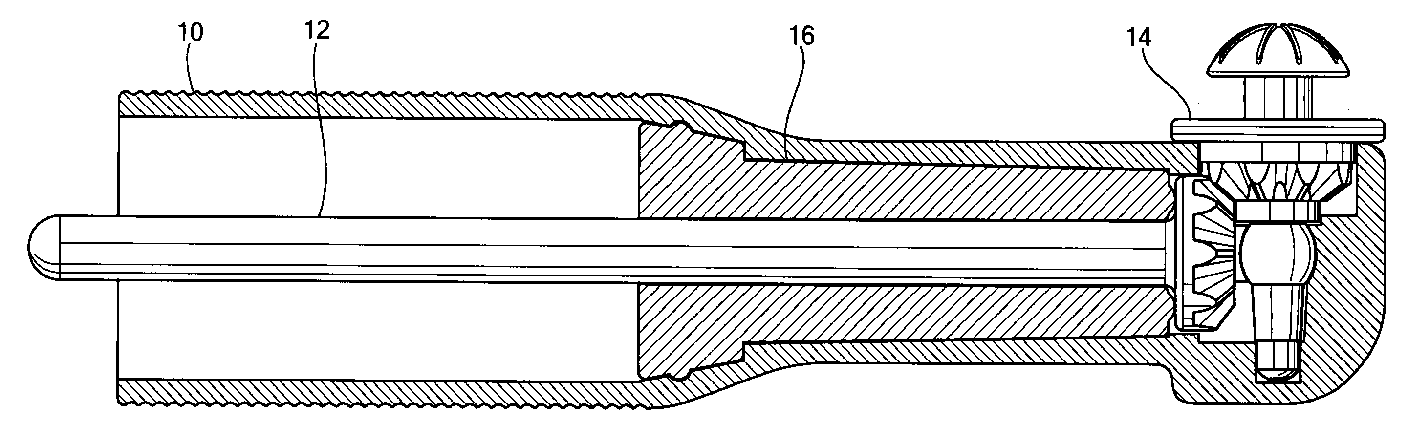
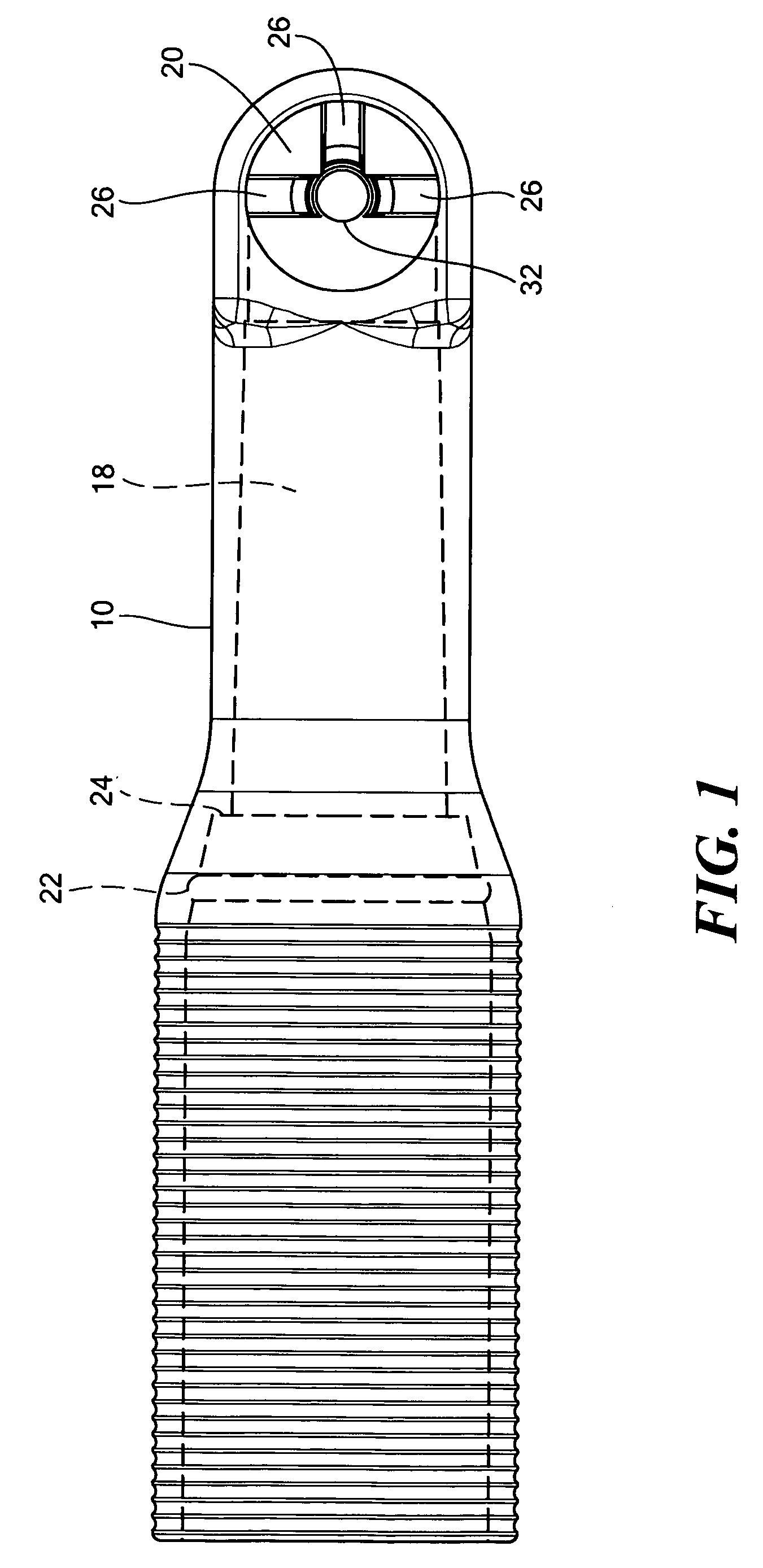
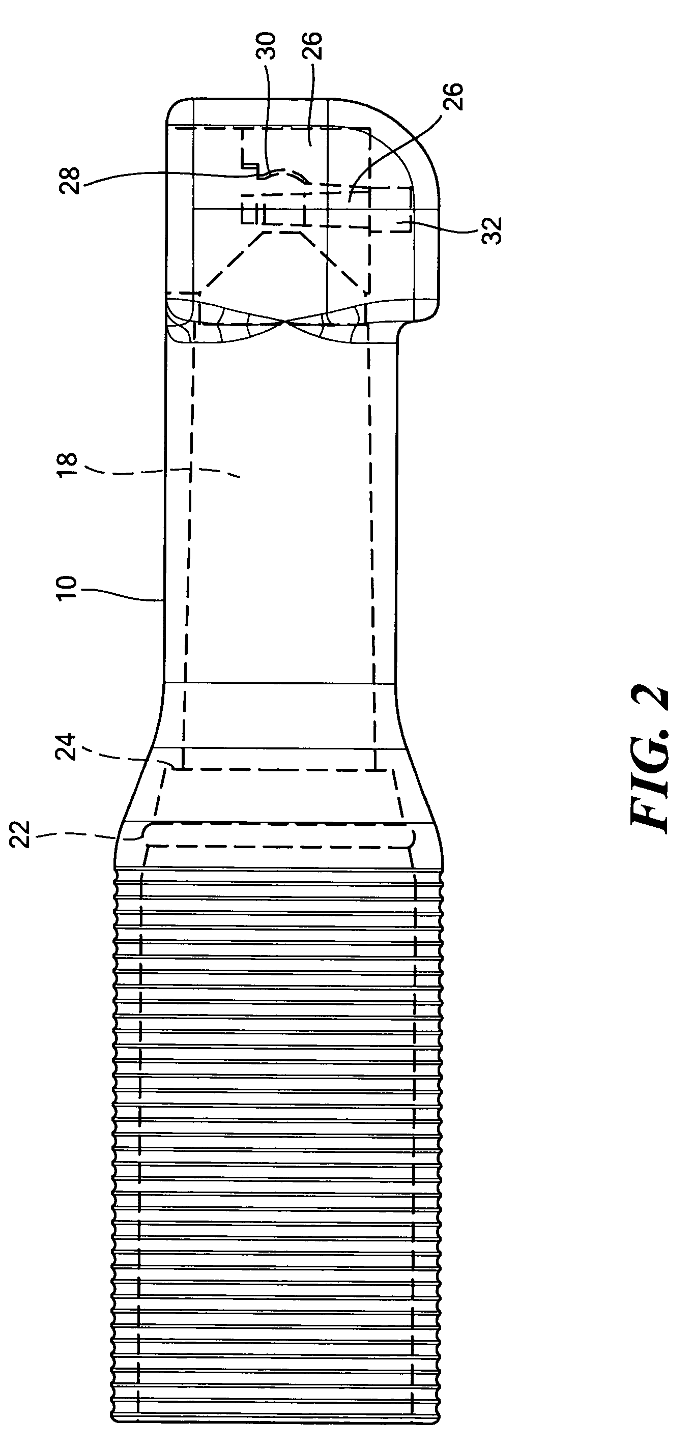
[0021] In an exemplary embodiment, the present invention provides a dental prophylaxis angle having a singular housing 10, a drive shaft 12, a rotor 14, and a collar 16. FIGS. 1 and 2 illustrate the singular housing 10 as a one-piece element which defines a first bore 18 extending through a length of the housing 10. A second bore 20 is in communication with and extends from the first bore 18 at a substantially perpendicular angle. The housing 10 further defines an annular groove 22 circumscribing a portion of the first bore 18, and a housing shoulder 24 disposed about a portion of the first bore 18 where the first bore 18 decreases in diameter.

[0022] A plurality of rotor bearing elements 26 is radially positioned within the second bore 20. Each rotor bearing element 26 includes an upper bearing surface 28, as well as having a spherical recess 30 on a surface of the bearing element that is substantially perpendicular to the upper bearing surface 28. In addition, the housing 10 inclu...


PUM


Abstract

The present invention provides a dental prophylaxis angle that includes a singular housing, a drive shaft, a rotor, and a collar. The housing may define a first bore, a second bore in communication with the first bore at a substantial angle thereto, and a third bore coaxial with the second bore. The drive shaft is positionable in the first bore, and the drive shaft may include a post, which may define a spherical depression. The rotor is positionable in the second bore, and may define a spherical bearing and a spherical tip. The collar defines an axial bore where the collar is positionable in the first bore such that a portion of the drive shaft is disposed within the axial bore.

Description

CROSS-REFERENCE TO RELATED APPLICATION [0001] N / A STATEMENT REGARDING FEDERALLY SPONSORED RESEARCH OR DEVELOPMENT [0002] N / A FIELD OF THE INVENTION [0003] The present invention relates to dental instruments, and more particularly to dental prophylaxis devices. BACKGROUND OF THE INVENTION [0004] Dental prophylaxis angles, generally referred to as “prophy angles,” are commonly used dental instruments providing rotation for dental tools such as brushes, prophy cups, or other receptacles used in polishing teeth. A prophy angle typically includes a housing having a neck and a head portion extending at approximately a 90° angle to the neck, which increases the ability of a dentist to reach various surfaces of the teeth of a patient. A drive shaft can be located within the housing and attached to a driven gear in the head of the prophy angle. Prophy angles are generally affixed to a handpiece, which connects the prophy angle to a drive source, thereby enabling a rotating motion of the driv...

Claims


Application Information

Patent Timeline
Patent Type & Authority Applications(United States)
IPC IPC(8): A61C3/06A61C1/08
CPCA61C17/005A61C17/16A61C3/06A61C1/12
Inventor CARRON, CHRIS J.GRITHER, DAVID G.
Owner AVID
Why Eureka
Try Eureka