Walk assisting device

a technology for walking assistance and support members, which is applied in the field of walking assistance devices, can solve the problems of cumbersome placement, practically impossible for a user with a leg impediment to put on the support members by oneself, etc., and achieve the effects of convenient and secure fastening of the hip support members on the user's body, easy adjustment of build differences, and easy adjustment of build

Active Publication Date: 2007-02-01
HONDA MOTOR CO LTD
View PDF8 Cites 30 Cited by
  • Summary
  • Abstract
  • Description
  • Claims
  • Application Information

AI Technical Summary

Benefits of technology

[0008] In this way, the walking assistance device can be formed by combining three separate members, and this makes it easier for the walking assistance device to be worn by a user. The three members can be chosen individually and this allows the walking assistance device to easily cope with differences in build or condition (degree of impediment) of the users.
[0009] According to the invention of claim 2, the hip support member comprises: a back support (4) extending from right and left iliac crests to a backside of a sacroiliac joint; and a pair of web parts (15) extending out from either right and left ends of the back support and connected to each other with a buckle (16) at a lower abdominal portion around a lower part of an abdominal muscle. In such a structure, it is possible to fasten the hip support member on the user's body easily and securely by just adjusting the tension of the web parts as desired. Further, because there is no part that needs to be fastened on the thigh, the hip support member can be easily worn to the hip of the user even while sitting on a chair.

Problems solved by technology

However, the prior art devices, such as those disclosed in the above publication, were quite cumbersome to put on, and it was practically impossible for a one having a leg impediment to put on the support member by oneself.

Method used


Image

  • Walk assisting device
  • Walk assisting device
  • Walk assisting device

Examples


Embodiment Construction

[0011] In the following, the present invention will be described in detail with reference to the appended drawings.

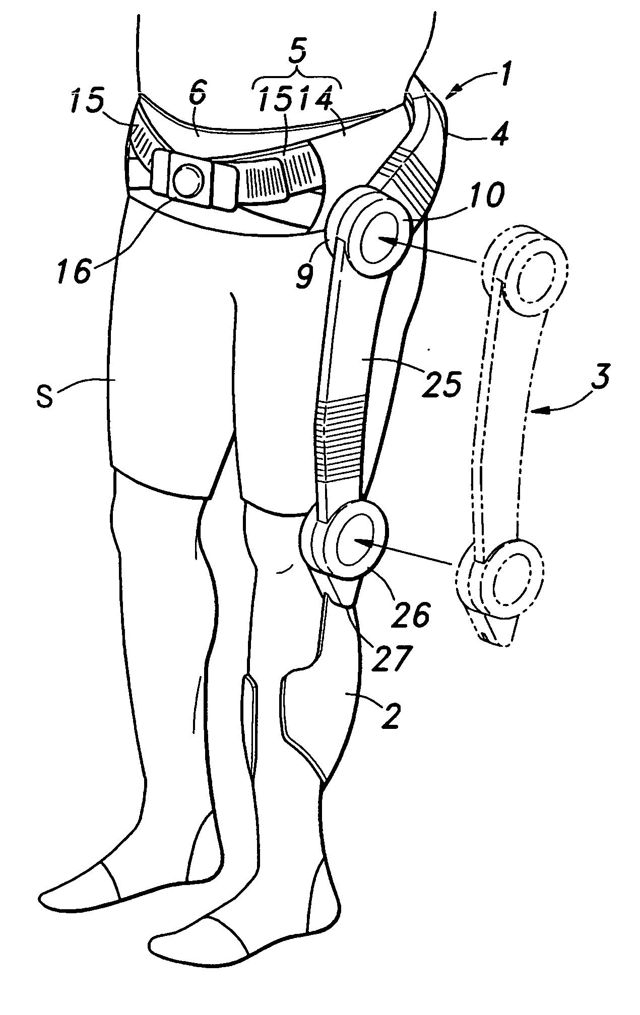
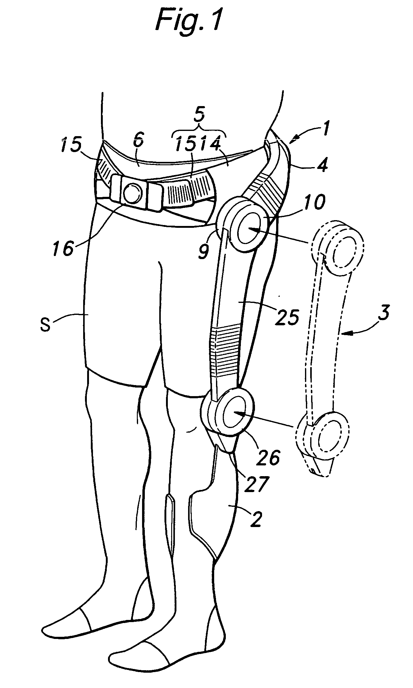
[0012]FIG. 1 shows a walking assistance device of the present invention as worn on a user's body. The walking assistance device consists of a hip support member 1, lower leg support member 2 and a drive unit 3, where the hip support member 1 and the lower leg support member 2 are secured on a lower limb and a rotational torque generated by the drive unit 3 is transmitted to the lower limb via the hip and lower leg support members, to whereby provide a force for supplementing a reduced muscle power.

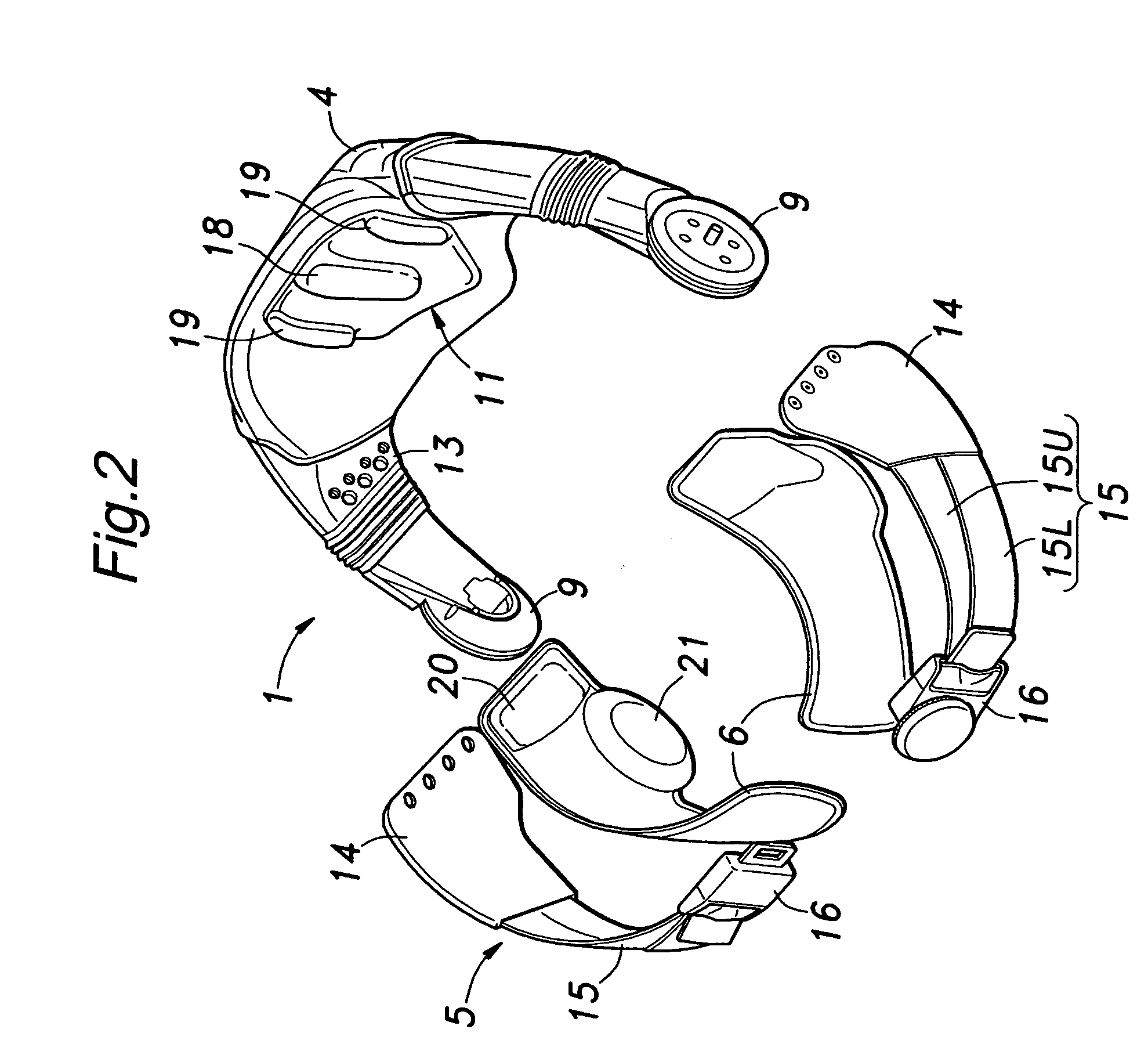
[0013] The hip support member 1 comprises a back support 4, belt portion 5 and lining portion 6, as shown in FIG. 2.

[0014] Additionally referring to FIG. 3, the back support 4 is substantially of the shape of letter-U as seen in plan view so that it abuts a region of the body extending from right and left iliac crests (front ends of the pelvic bone) 7 to the backside of the...


PUM


Abstract

There is provided a walking assistance device equipped with an assisting force generator disposed on a side of each of a hip joint and a knee joint, comprising: a hip support member (1) having an attachment means (hip drive source mount 9) capable of repeatedly attaching and detaching a hip joint assisting force generator (hip joint actuator 10); a lower leg support member (2) having an attachment means (knee drive source mount 27) capable of repeatedly attaching and detaching a knee joint assisting force generator (knee joint actuator 26); and a drive unit (3) formed by integrally joining the hip joint assisting force generator and the knee joint assisting force generator via a link bar (25), wherein after the hip support member and the lower leg support member are fitted on a user's body, the assisting force generators of the drive unit are connected to the corresponding attachment means.

Description

TECHNICAL FIELD [0001] The present invention relates to a walking assistance device for providing an assisting force to the movement of the nip joint and knee joint. BACKGROUND ART [0002] Various proposals have been made for a walking assistance device that is adapted to mount an actuator to the hip joint or knee joint of a person having a walking impediment due to injury, disease or weakened muscle resulting from aging, so that the power from the actuator can be used to assist the movement of the lower limb. [0003] Conventionally, in such a walking assistance device, it was necessary to fasten corset-like support members onto the hip, thigh and lower leg portions to securely mount rotational actuators on a side of the hip joint and knee joint and transmit the drive torque from the rotational actuators to the lower limb. [0004] Patent Publication 1: JPA No. 58-163364 (FIGS. 1-4) DICLOSURE OF THE INVENTION Objects to be Achived by the Invention [0005] However, the prior art devices, ...

Claims


Application Information

Patent Timeline
Patent Type & Authority Applications(United States)
IPC IPC(8): A61H1/02A61H1/00A61F5/01A61H3/00
CPCA61F5/0102A61H3/008A61H2201/165A61H1/0255A61H2201/1642A61H2201/0192A61H2201/1215A61H2201/163A61H3/00
Inventor KATOH, HISASHIKOYAMA, TAIJI
Owner HONDA MOTOR CO LTD
Why Eureka
Try Eureka