
External condition control device based on measurement of brain functions

a condition control and brain function technology, applied in the field of external condition control devices based on brain functions, can solve problems such as difficulty in operation, physical handicapped people operating devices, and decrease in subject's feeling, so as to improve the reliability, improve the repeatability of measurement operations, and propagate the effect of a single sensor's malfunction

Inactive Publication Date: 2012-05-08
HITACHI LTD
View PDF21 Cites 15 Cited by
  • Summary
  • Abstract
  • Description
  • Claims
  • Application Information

AI Technical Summary

Benefits of technology

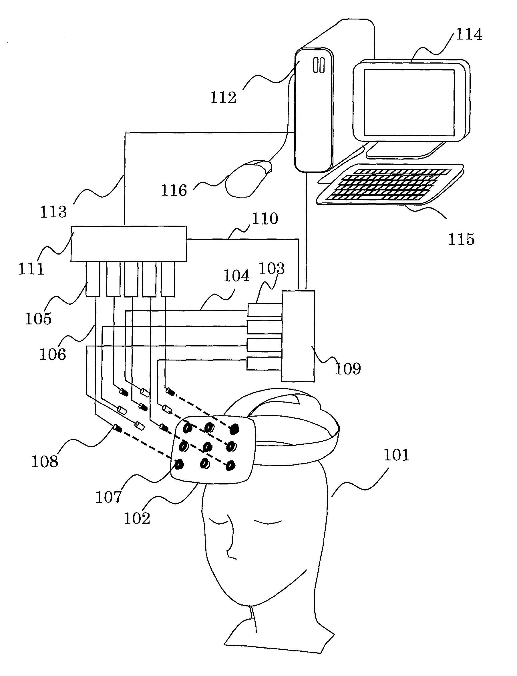
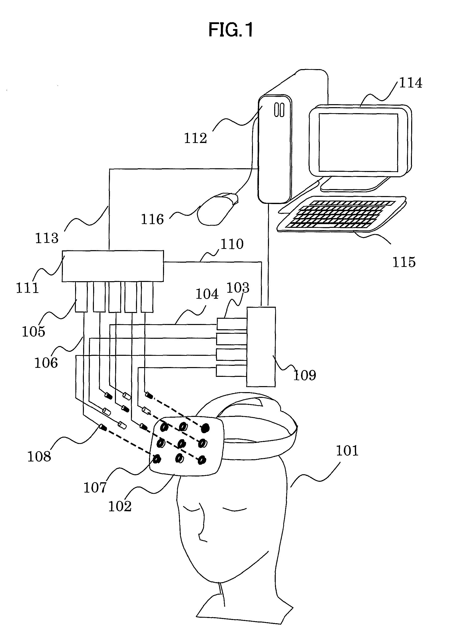
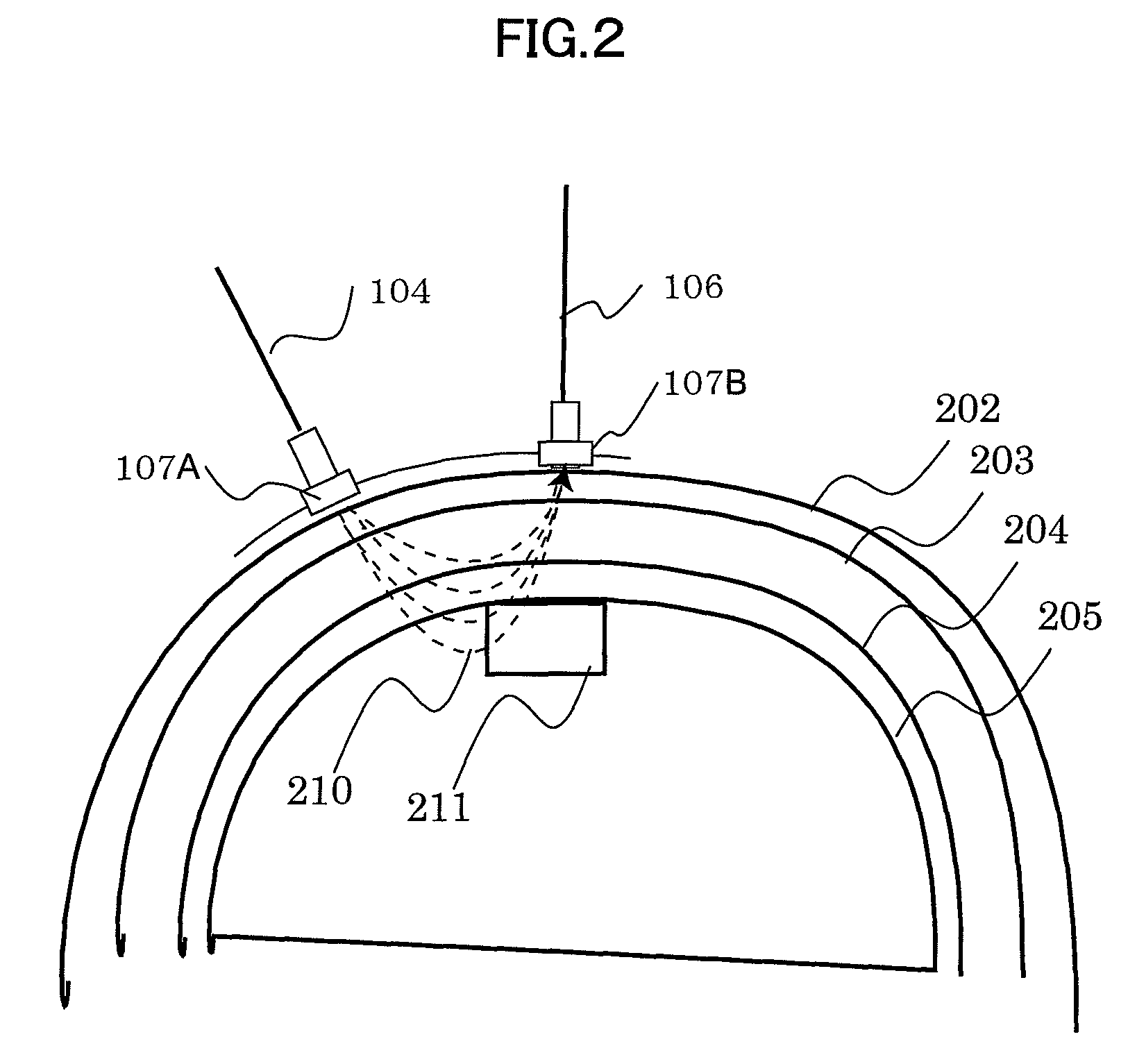
The present invention relates to an external condition control device based on measurement of brain functions using optical fibers. The device includes a helmet with optical fibers connected to a light projector and a light detector. The light projector emits light to the scalp of the subject, and the light is scattered and absorbed by the skull, cerebral cortex, and other living body tissues, resulting in a gradual loss of light intensity. The light detector picks up the scattered and absorbed light and sends it to a control device for analysis. The control device manages and controls the output light intensity. The device can estimate changes in blood flow caused by brain activities. The technical effect of the invention is to provide a non-invasive and efficient tool for controlling external conditions based on brain function measurements.

Problems solved by technology

However, the input devices operated by manual operation of a human operator may temporarily hinder the attention concentrated on another input operation or may decrease the feeling of the subject (i.e. an operator of a device or a player of video game) as if he or she were actually present at the site.
Also, difficulties may arise when a physically handicapped person operates the device.
However, in the measurement method, by which it is necessary to embed and bury an implant device by putting it into human body (invasive method), there is always a possibility to cause side effects (adverse effects).

Method used


Image

  • External condition control device based on measurement of brain functions
  • External condition control device based on measurement of brain functions
  • External condition control device based on measurement of brain functions

Examples


embodiment 1

[0065]FIG. 6 is a schematical drawing to show Embodiment 1 of an external control device based on bio-optical measurement according to the present invention. The component element with the same function as shown in FIG. 1 is referred by the same symbol. The system of calculation processing mechanism as shown in Embodiment 1 comprises information processing devices including an input unit 112, an information processing unit 601, and an output unit 602. These information processing devices are mutually connected to a network and can give and take input / output results to and from each other. As the information processing devices of this system, various types of general-purpose calculation devices such as a personal computer (PC) as widely known and a built-in type microcomputer module can be used.

[0066]It is also possible to design so that processing of the input unit 112, the information processing unit 601, and the output unit (output module) 602 can be carried out as software module...

embodiment 2

[0151]In the Embodiment 2, subroutine module in the real-time operation phase mode in computer is executed by actual devices. FIG. 18 is a perspective view to explain an example of the device actually operated. In the Embodiment 2, instead of the position of the cursor used in the Embodiment 1, position and angle of an arm 1801A are controlled in a selection device1801 designed in form of a shovel. In the Embodiment 1, the background moves. In the Embodiment 2, a belt conveyor 1803 carrying an object 1602 on it moves in the direction of thick arrow. The objects 1802 are periodically discharged to the belt conveyor 1803 from an object discharger 1805. Holes 1804 are disposed on the belt conveyor 1803. By moving an arm 1801A into the hole 1804 at adequate timing, the object can be dropped to a first collector 1806 from the belt conveyor 1803. The object, which was not dropped to the first collector 1806 by the selection device 1801, is dropped to a second collector 1807.

[0152]FIG. 19 ...


PUM

PropertyMeasurementUnit
distanceaaaaaaaaaa
near infrared spectroscopyaaaaaaaaaa
weightsaaaaaaaaaa

Abstract

The present invention is helpful in improving stability of repeated measurement and can be applied with high reliability for operations of devices for measurement based on brain functions. A module 801 (a sampler) receives measurement data at each of the measuring points based on information of cerebral blood amount sent from an input unit. The information data accumulated in this sampler are processed by filtering at a secondary agent 803 and a tertiary agent 804 and are analyzed. The synthesizer 802 integrates output information of each agent by weighted linear sum and transmits the data as an output data 602 to the device and operates the device.

Description

FIELD OF THE INVENTION[0001]The present invention relates to an external condition control device based on measurement of brain functions. In particular, the invention relates to a biological (living body) control device, in which an output signal of an information input device based on a bio-optical measurement method is used as an input signal for an external device to performs various types of control operations.BACKGROUND ART[0002]An external condition control device based on measurement of brain functions (also called “biological control device”) is operated by opto-biological measurement method and biological input device, and it is applied for operation of alarm device to give warning on physical conditions of a subject on test such as sleeping or decline of attentiveness and for the control of various types of devices without using button, mouse or handle for the control of the devices in the external condition to match the state of consciousness and unconsciousness of the s...

Claims


Application Information

Patent Timeline
Patent Type & Authority Patents(United States)
IPC IPC(8): A61B6/00A61B10/00G01N21/17G01N21/35G01N21/3577G01N21/359G06F3/01
CPCG06F3/011A61B5/04842A61B5/14553A61B5/378
Inventor UTSUGI, KEIMAKI, ATSUSHI
Owner HITACHI LTD
Learn More