Tape measure

a tape measure and tape technology, applied in the field of tape measures, can solve the problems of inefficiency of use of conventional tape measures, and achieve the effect of shortening the duration of reeling

Inactive Publication Date: 2007-02-08
MURATEC KDS
View PDF5 Cites 2 Cited by
  • Summary
  • Abstract
  • Description
  • Claims
  • Application Information

AI Technical Summary

Benefits of technology

[0006] Accordingly, an object of the present invention is to provide a tape measure which is adapted to e

Problems solved by technology

Thus, the conventional ape me

Method used


Image

  • Tape measure
  • Tape measure
  • Tape measure

Examples


Embodiment Construction

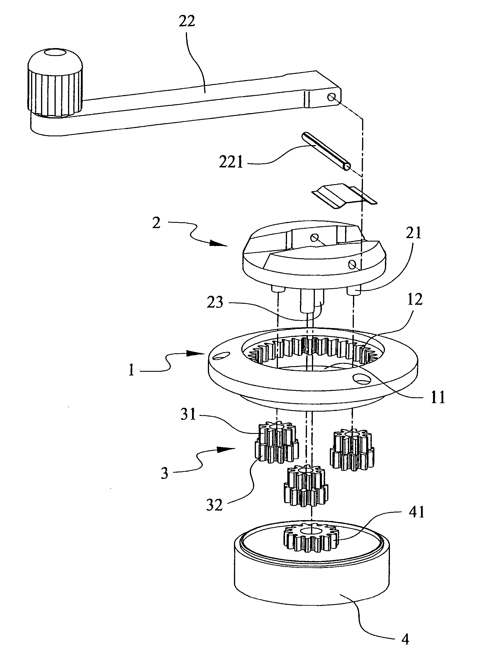
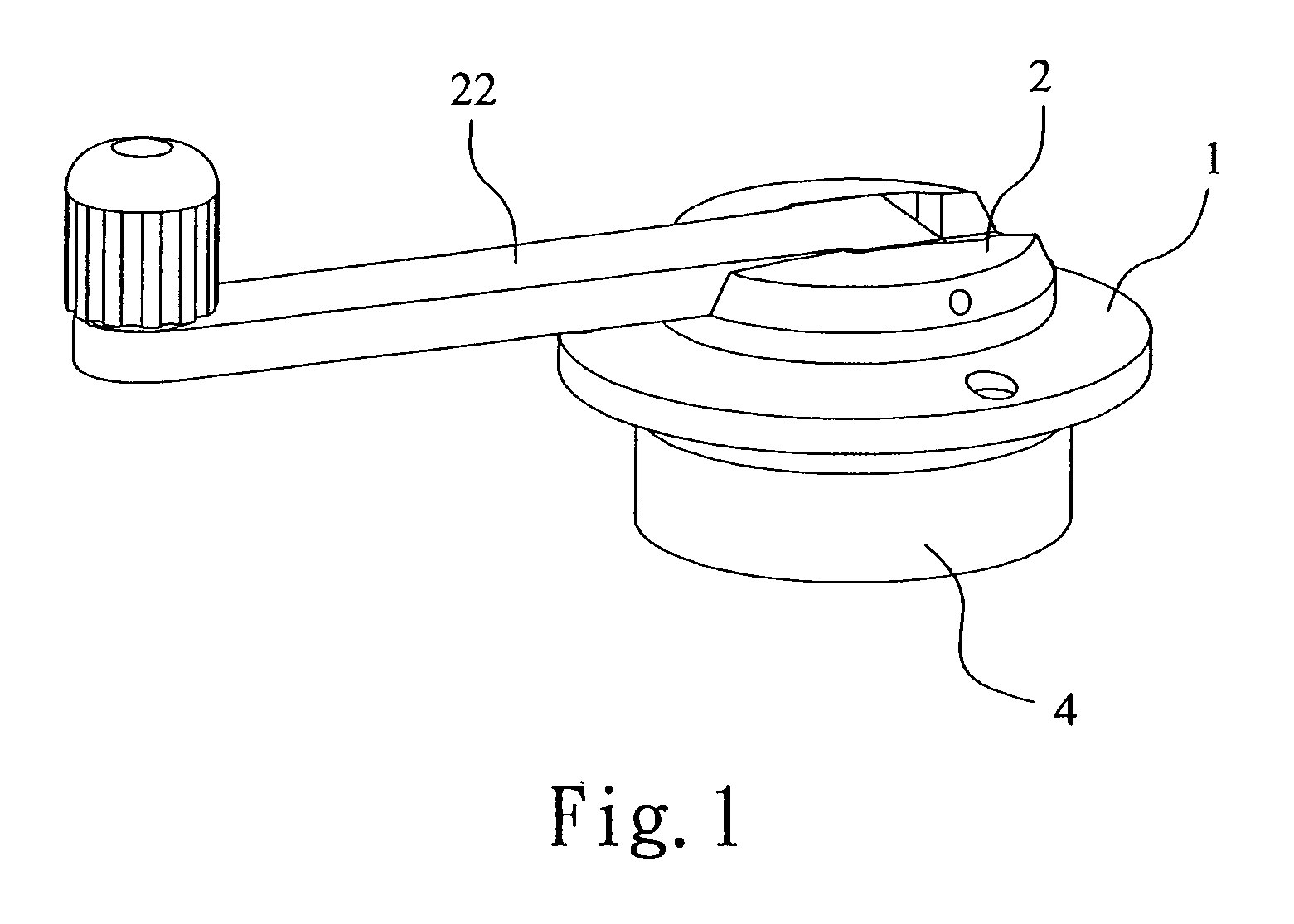
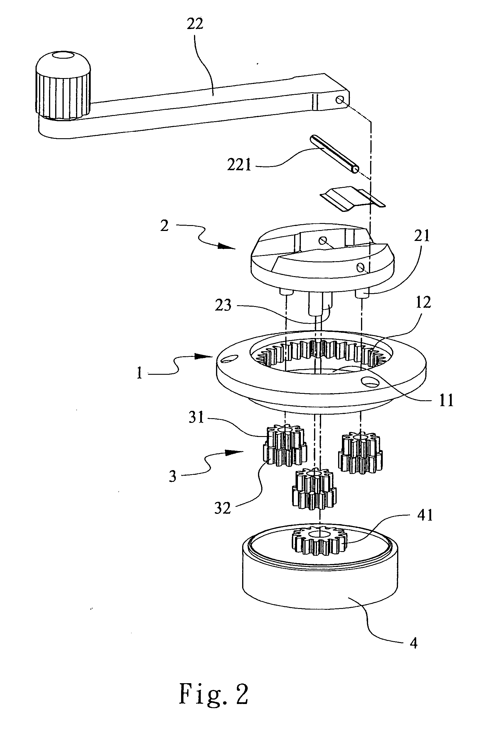
[0014] Referring to FIGS. 1-2, a tape measure of the present invention includes a mounted wheel 1, a pivot portion 2, rotation members 3, transmission wheel 4 and a blade container 5 (not shown).

[0015] The mounted wheel 1 has an opening 11 thereon wherein a serrated portion 12 being arranged around inner sides thereof. The pivot portion 2 being fitted into the opening 11 has an axis 23 and a plurality of posts 21 on a side thereof and a driving bar 22 on another side thereof wherein the driving bar 22 is connected with a rod 221 located thereon.

[0016] The rotation members 3 being rotatably mounted on the posts 21 includes a first gear 31 and a second gear 32 in which the first and the second gear 31, 32 are stacked with each other, wherein the first gear 31 is engagable with the serrated portion 12 and coaxially shrinks from outer flanges of the second gear 32.

[0017] The transmission wheel 4 has an operation gear 41 which operates cooperatively with the axis 23 and which is engag...


PUM


Abstract

A tape measure of the present invention includes a mounted wheel, a pivot portion, rotation members, transmission wheel and a blade container wherein the rotation members include a first gear and a second gear. The mounted wheel has a serrated portion being arranged around inner sides thereof. The pivot portion being fitted into the opening has an axis and a plurality of posts on a side thereof and a driving bar on another side thereof. The transmission wheel has an operation gear. By the first gear and the second gear respectively and cooperatively operate with the mounted wheel and the transmission wheel, the transmission wheel is therefore rotated four circles as the pivot portion is rotated one circle, so duration of reeling the measuring blade becomes less.

Description

BACKGROUND OF THE INVENTION [0001] (a) Field of the Invention [0002] The present invention relates to a tape measure being adapted to enclose a spooled measuring blade and more particularly, to a tape measure having structure for quickly reeling the blade. [0003] (b) Description of the Prior Art [0004] Referring to FIG. 5, a conventional tape measure includes a casing 6 with a toothed part 61, a pivot part 7 having a plurality of sleeves 71 on a side thereon, a plurality of wheels 8 being fitted on the sleeves 71 and being engagable with the toothed part 61, and a driving part 9 having a driving wheel 91 being engagable with wheels 8; by rotating the pivot part 7 to enable the wheels 8 rotating, thereby the driving part 9 being accordingly for reeling blades. [0005] The conventional tape measure, however, can reel blades; duration of reeling blade is too long which is that the wheels 8 forms only single layer; thereby, when the wheels 8 rotate cooperatively with the toothed part 61 ...

Claims


Application Information

Patent Timeline
IPC IPC(8): B65H75/44
CPCB65H2403/481G01B2003/1043G01B2003/1025G01B3/1005G01B3/1043
Inventor LIN, PING-LIN
Owner MURATEC KDS
Why Eureka
Try Eureka