
Stand of display device

Inactive Publication Date: 2007-02-08
LG ELECTRONICS INC
View PDF6 Cites 33 Cited by
  • Summary
  • Abstract
  • Description
  • Claims
  • Application Information

AI Technical Summary

Benefits of technology

[0013] It is an object of the present invention to provide with a stand capable of preventing a capability of tension springs from being degraded in an auxiliary link even when an overweight is repeatedly applied to a spring such as a case that the folding of a stand continues for a long time.
[0015] Furthermore, it is another object to provide a stand with a high product reliability to improve the convenience of a user with a simple configuration.
[0019] It is possible to prevent a possibility of a tension spring from being degraded even when the folding of a stand lasts for a long period by the folding due to a configuration of the present invention. In addition, if the stand is folded, a main spring of the stand can be fixed itself to simplify the structure of the stand and the stand can be folded and disassembled conveniently.
[0020] In addition, a stand can be conveniently used by the configuration suggested as above and the operational reliability of the stand is improved when the user operates the stand.

Problems solved by technology

Therefore, when the stand is used as a desk-type, the stand does not appropriately apply a restoring force at the state that a tension spring is plastic-deformed, resulting in inconvenience of movements of the stand.
This problem may occur even when the stand is used as a desk-type stand and a weight is applied to a tension spring, because a user often adjusts a height of the stand.
However, the conventional fixing devices are additionally formed at a base of a stand, and the costs for manufacturing required for configuring the base portion are increased.
In addition, in order to disassemble the folded state of the stand, additional operations such as pulling a disassembling device lever are required, and this may cause an inconvenience of users.

Method used


Image

  • Stand of display device
  • Stand of display device
  • Stand of display device

Examples


Embodiment Construction

[0029] Reference will now be made in detail to the preferred embodiments of the present invention, examples of which are illustrated in the accompanying drawings.

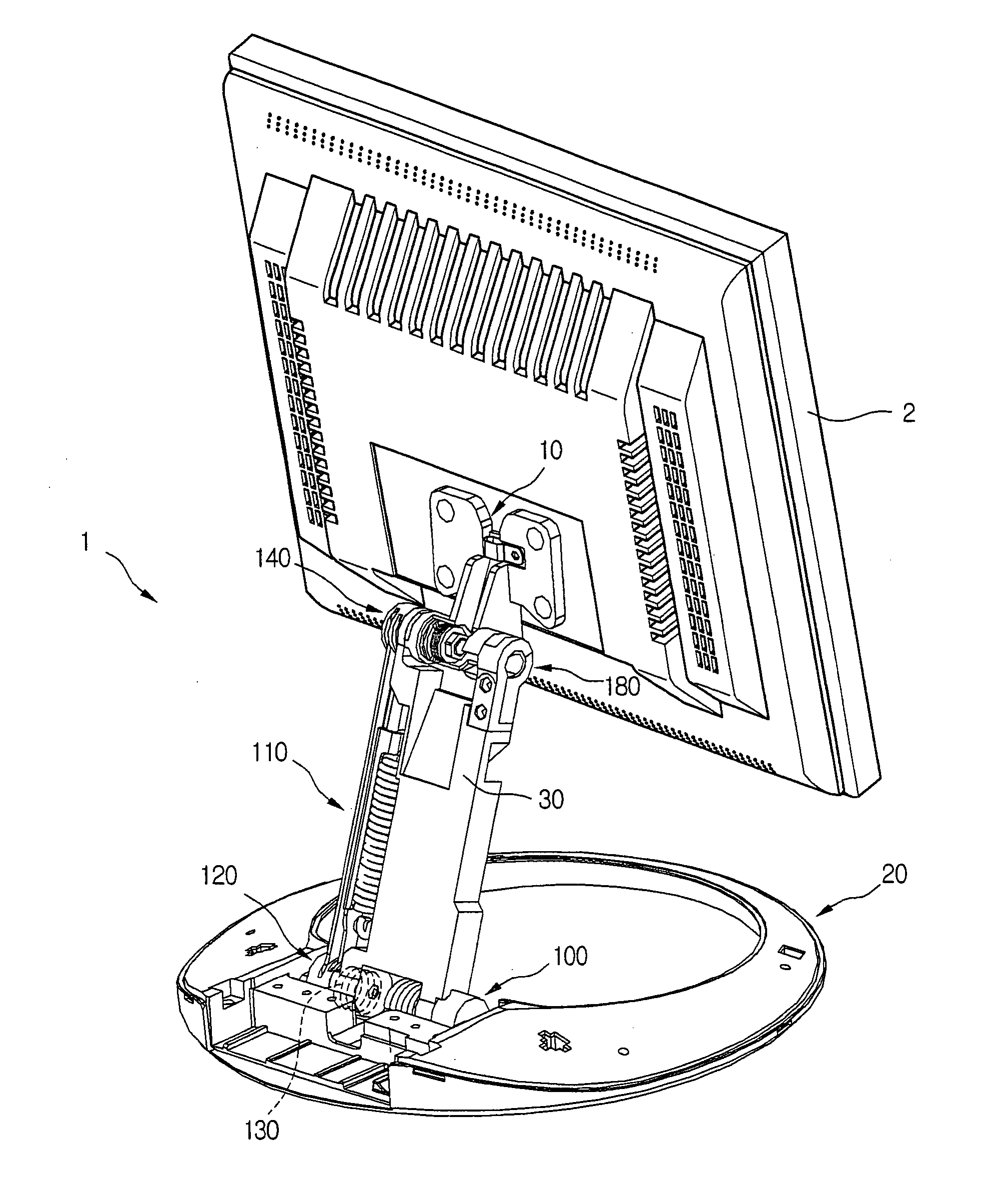
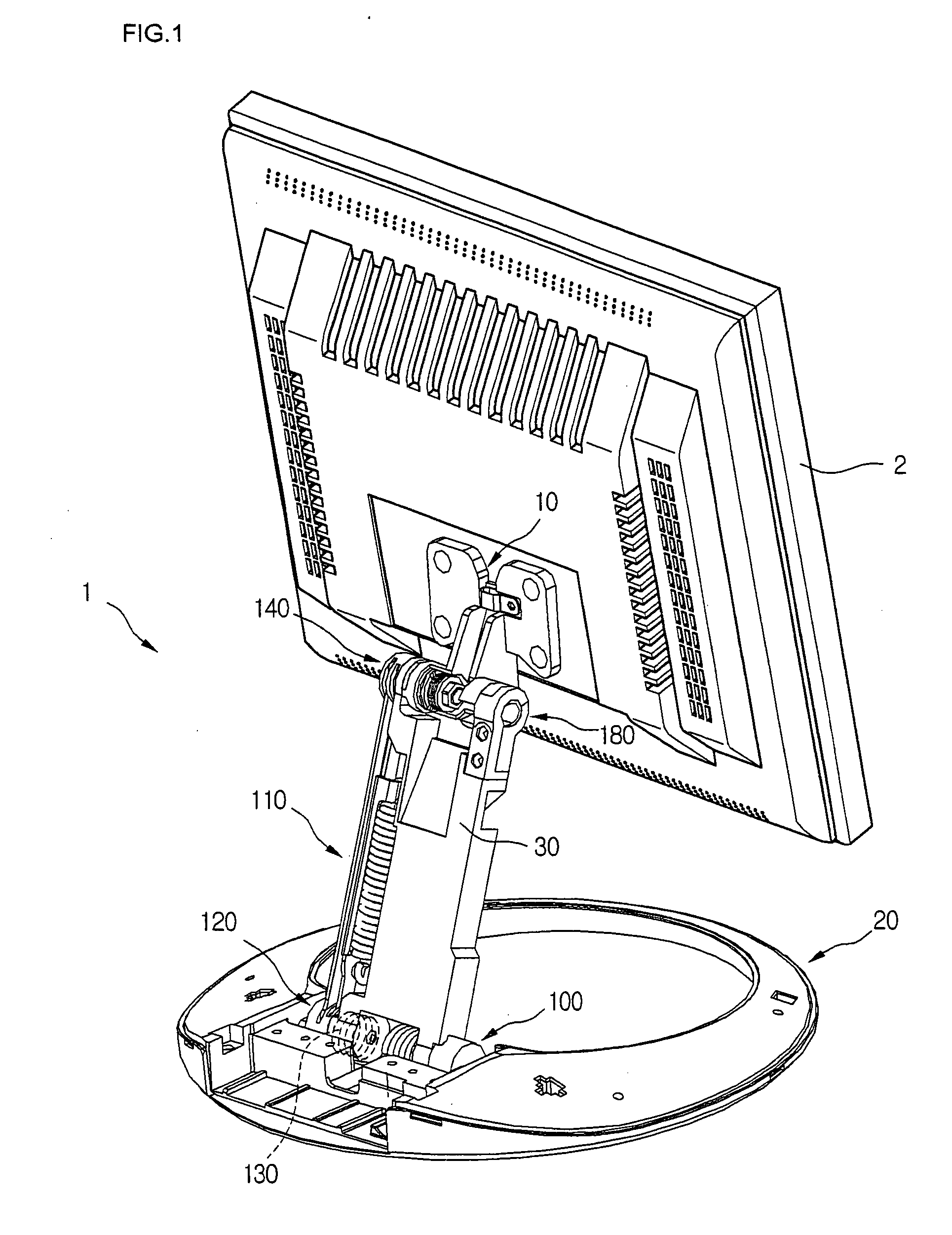
[0030]FIG. 1 is a rear surface perspective view of a display device in accordance with the present invention.

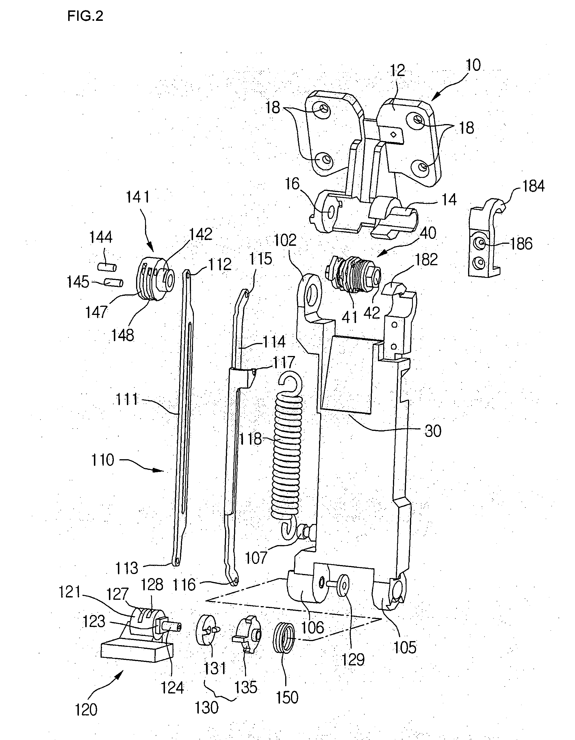
[0031] Referring to FIG. 1, the stand comprises: a supporting portion 10 fixed at a rear surface of a visual display device 2 such as an LCD monitor to support the visual display device 2, a base portion 20 for mounting the visual display device 2 at a bottom surface and a main link 30 of which both ends are rotatively connected to the supporting portion 10 and the base portion 20. In addition, an auxiliary link portion 110 connected between the supporting portion 10 and the base portion 20 is positioned at a side of the main link 30, or a left side with reference to FIG. 1. A folding stopper 130 equipped with the base portion 20 is provided at a bottom surface of the auxiliary link portion 110 so as to fix the fol...


PUM


Abstract

Provided is a stand of a display device which can be used both as a wall-mounted type and a desk-type for improving an operational reliability and a convenience of users, comprising: a display device; a supporting portion supporting a rear surface of the display device; a base placing the display device at a different position; a main link portion connected between the supporting portion and the base by a hinge so that the supporting portion can be rotated with respect to the base; an auxiliary link portion connected between the supporting portion and the base by a hinge at a side of the main link portion for maintaining an angle of a display device when the main link portion is rotated; an elastic member of which both ends being connected at the auxiliary link portion and the main link portion, respectively, for controlling vertical movements of the display device; and a stopping portion for fixing a folding state when the main link portion is folded.

Description

BACKGROUND OF THE INVENTION [0001] 1. Field of the Invention [0002] The present invention relates to a stand of a display device, and particularly, to stands capable of operating both as a desk-type stand and a wall-mounted type stand. More particularly, the present invention relates to a stand of a visual display device, since the stand is changed into a desk-type and a wall-mounted type in accordance with its operational state, it is possible to prevent an operational capacity of the stand from being decreased when tensions and restorations of the springs are repeatedly performed, conveniently perform the operations of the wall-mounted stand and maintain a fixed state of the folded stand to be reliable. [0003] 2. Description of the Related Art [0004] In general, a stand comprises a supporting portion locating at a rear surface of a main body of a display device on which an image is displayed, a base portion locating at the supporting portion such as a bottom or a wall and a link p...

Claims


Application Information

Patent Timeline
IPC IPC(8): A47G29/00
CPCF16C11/10F16M11/04F16M11/10F16M2200/08F16M2200/024F16M2200/044F16M11/2021Y10S248/917G06F1/1601
Inventor BAEK, JIN UK
Owner LG ELECTRONICS INC
Learn More