Ground fault circuit interrupter (GFCI) end-of-life (EOL) status indicator
- Summary
- Abstract
- Description
- Claims
- Application Information
AI Technical Summary
Benefits of technology
Problems solved by technology
Method used
Image
Examples
Embodiment Construction
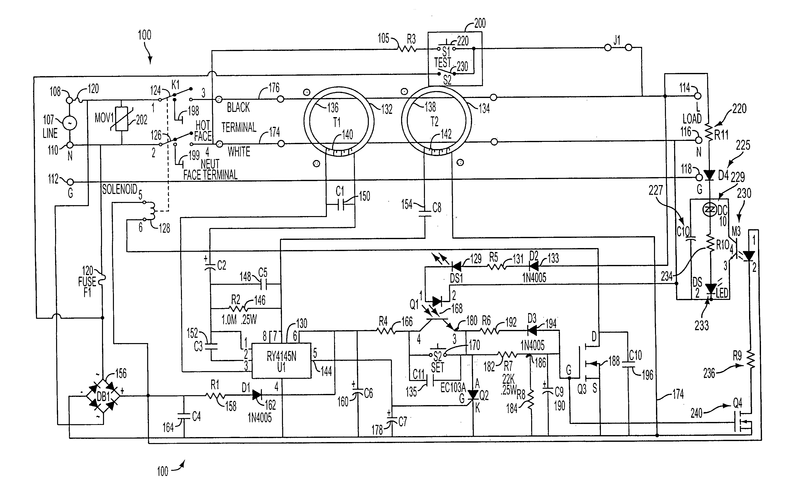
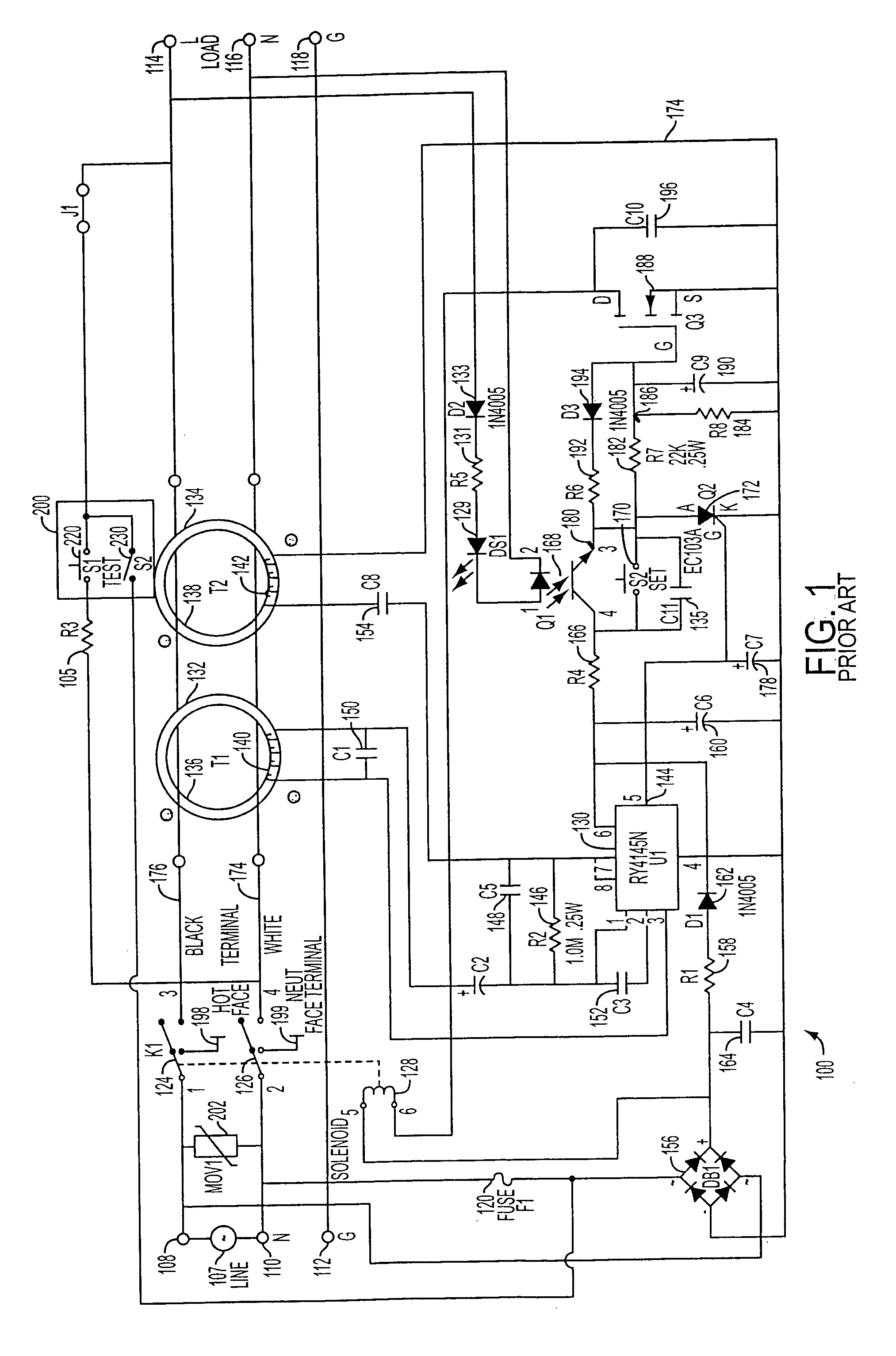
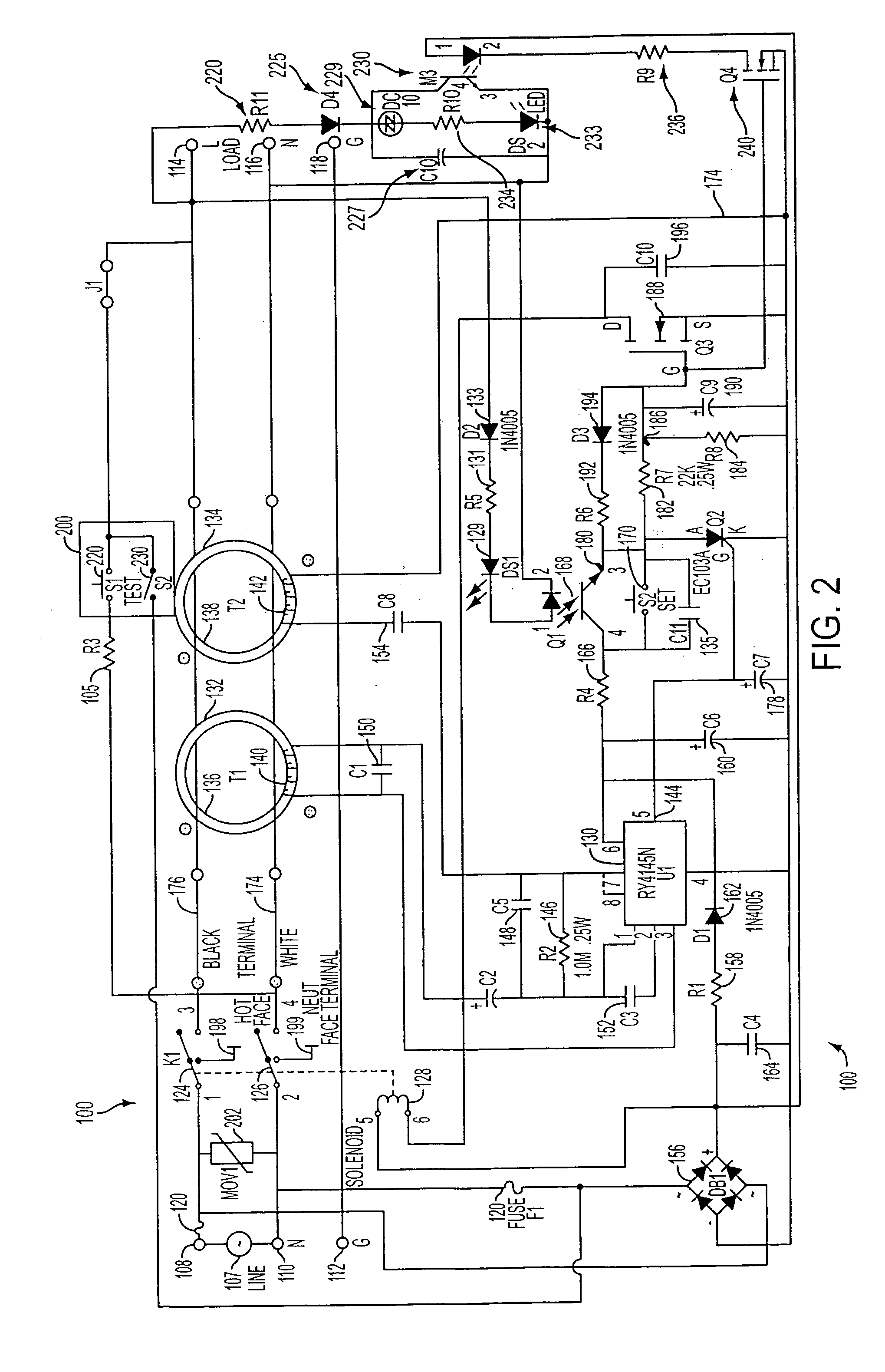
[0021] The typical operation of a conventional GFCI receptacle will be explained with reference to FIG. 1. Generally, it can be seen that a conventional ground fault circuit interrupter (GFCI) device 100 has an interrupt module comprising a relay with contacts 124 and 126, and a test switch 200 having primary test switch contacts 220 and secondary test switch contacts 230. The contacts 124 and 126 break a plurality of conductive paths between source terminals 108, 110 and load terminals 114, 116 of an AC receptacle in response to an imbalance of current flow in the paths.
[0022] The GFCI device 100 includes the pair of input (or source) terminals 108 and 110 which are adapted to be connected to the line (L) and neutral (N) terminals, respectively, of an AC power source 107. Within the GFCI device 100, a first conductor 176 connects the AC line input terminal 108 to a corresponding AC line output (or load) terminal 114, and a second conductor 174 connects the AC neutral input termina...
PUM
 Abstract
Description
Claims
Application Information
 - R&D
- Intellectual Property
- Life Sciences
- Materials
- Tech Scout
- Unparalleled Data Quality
- Higher Quality Content
- 60% Fewer Hallucinations
Browse by: Latest US Patents, China's latest patents, Technical Efficacy Thesaurus, Application Domain, Technology Topic, Popular Technical Reports.
© 2025 PatSnap. All rights reserved.Legal|Privacy policy|Modern Slavery Act Transparency Statement|Sitemap|About US| Contact US: help@patsnap.com


