
Azimuth measurement device and azimuth measurement method

a technology of azimuth measurement and measurement method, which is applied in the direction of navigation instruments, navigation by terrestrial means, instruments, etc., can solve the problems of long time taken to correct the offset, improper calculation of the offset value, and inability to accurately calculate the offset. the effect of enhancing the calculation accuracy

Active Publication Date: 2007-02-15
ASAHI KASEI ELECTRONICS CO LTD
View PDF5 Cites 22 Cited by
  • Summary
  • Abstract
  • Description
  • Claims
  • Application Information

AI Technical Summary

Benefits of technology

[0040] According to the azimuth measurement device or the azimuth measurement method of the invention, on the basis of the reliability information calculated by the reliability information calculation means, the acceptance threshold value at the time of calculating the offset information can be gradually tightened. When the quick response of the system is demanded as when it is started up, the calculation accuracy can be enhanced by setting the aforementioned acceptance threshold at a higher (or looser) value at first and by reducing (or tightening) the acceptance threshold gradually. At the same time, the response or measurement accuracy of the system can also be changed according to the situations even if the minimum values of the number or change of the data composing the magnetic data group for calculating the offset.

Problems solved by technology

Alternatively, the user of the azimuth measurement device may evaluate that the calculated value of the offset is improper, and may require a recalculation intentionally.
In case, however, the offset highly changes, a long time is taken till the correct offset is adopted.
For these reasons, a plurality of specifications such as the response rate or accuracy required for the azimuth measurement device are hard to satisfy at the same time, if the adoption and discard of the reference point are determined by using one acceptance threshold at all times.

Method used


Image

  • Azimuth measurement device and azimuth measurement method
  • Azimuth measurement device and azimuth measurement method
  • Azimuth measurement device and azimuth measurement method

Examples


Embodiment Construction

[0050] Hereinafter, embodiments of the invention are described with reference to the accompanying drawings.

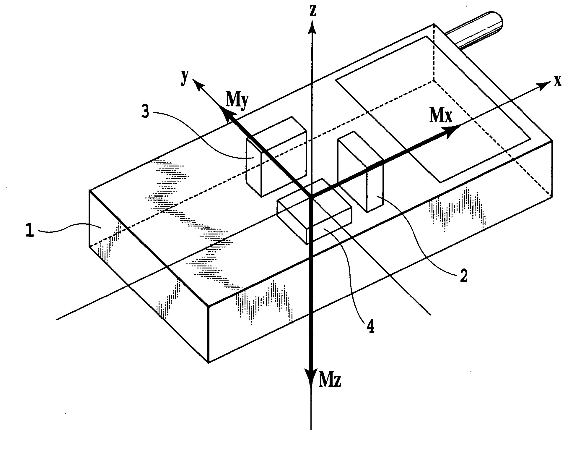
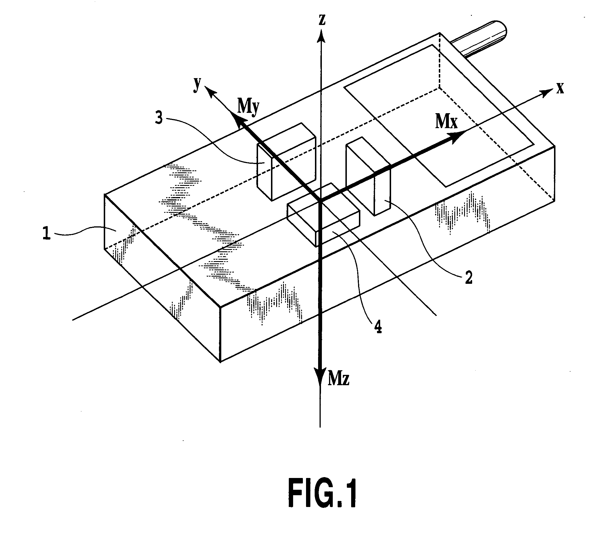
[0051]FIG. 1 is a configuration diagram for explaining one embodiment of an azimuth measurement device having a 3-axis magnetic sensor according to the invention. Numeral 1 designates an azimuth measurement device; numeral 2 an X-axis magnetic sensor; numeral 3 a Y-axis magnetic sensor; and numeral 4 a Z-axis magnetic sensor. In this azimuth measurement device 1, as shown in FIG. 1, the X-axis magnetic sensor 2, the Y-axis magnetic sensor 3 and the Z-axis magnetic sensor 4 having sensitive faces directed in their individual directions are arranged to intersect with each other at a right angle. The X-axis magnetic sensor 2 is configured to produce its output Mx; the Y-axis magnetic sensor 3 is configured to produce its output My; and the Z-axis magnetic sensor 4 is configured to produce its output Mz. Here, the magnetic sensors may be any such as a Hall element so long as they ...


PUM


Abstract

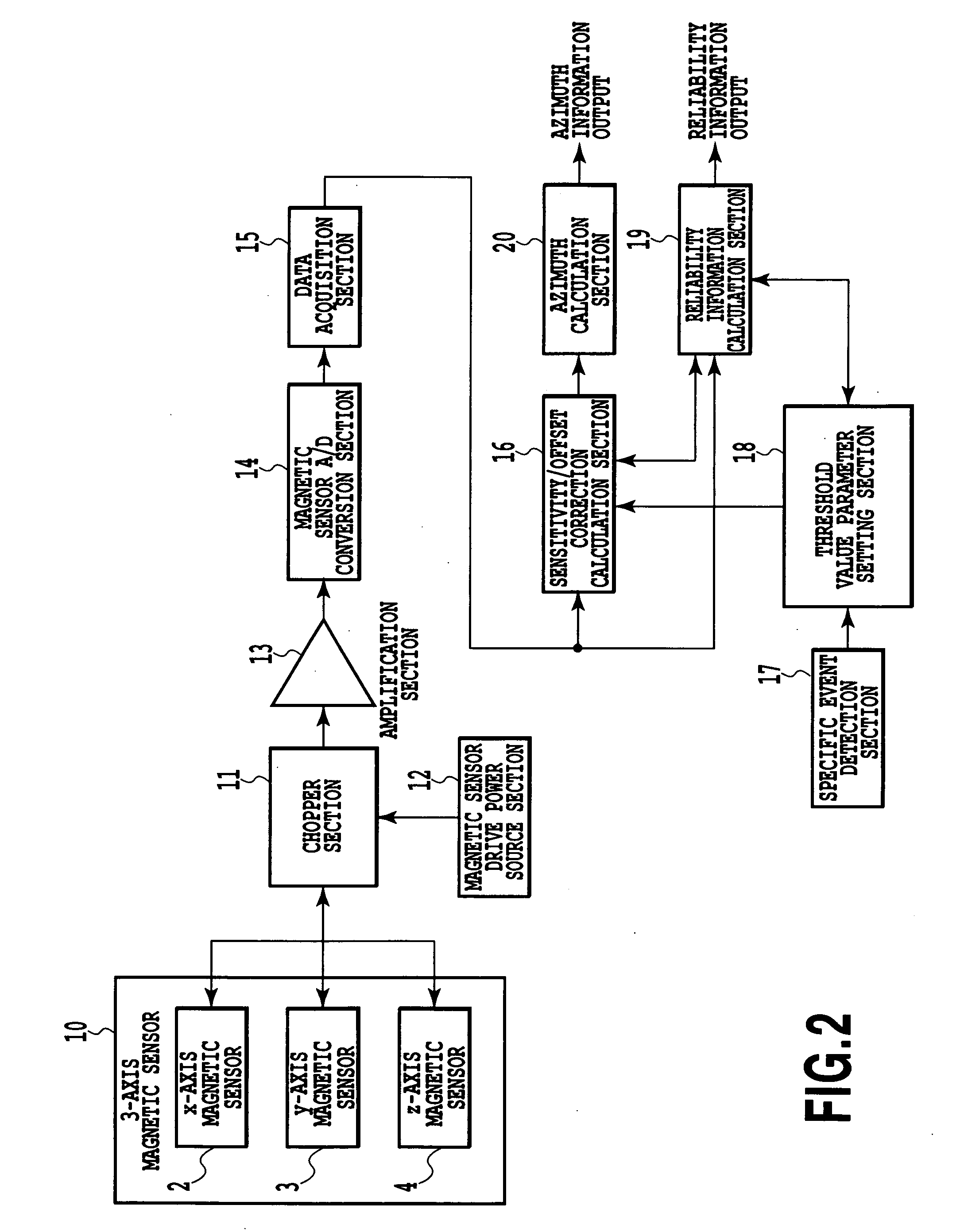
There are provided an azimuth measurement device and its method for realizing an update of an offset calculated from the data acquired by azimuth measurement. A geomagnetism output measured by a 3-axis magnetic sensor is amplified and input to an A / D conversion section. A chopper section is arranged for switching the terminals for driving an X-axis, Y-axis and a Z-axis magnetic sensor and applies drive voltage output from a drive power source section to the X-axis, the Y-axis and the Z-axis magnetic sensor. The output amplified value amplified by the amplification section is converted from an analog signal to a digital signal by the A / D conversion section and then is input to a sensitivity / offset correction calculation section. Output data from this sensitivity / offset correction calculation section is input to an azimuth calculation section and the corresponding azimuth information is output. A reliability information calculation section outputs reliability information.

Description

TECHNICAL FIELD [0001] The present invention relates to an azimuth measurement device and an azimuth measurement method and, more particularly, to an azimuth measurement device and an azimuth measurement method for calculating an offset quickly or highly accurately from the magnetic data group acquired for measuring an azimuth, in accordance with the situations. BACKGROUND ART [0002] For the azimuth measurement device for detecting the geomagnetism to calculate the azimuth, it is important to discriminate a geomagnetism (i.e., a steady magnetic field) and such a magnetic field other than the geomagnetism as is generated by a magnet or the like fixed in the azimuth measurement device. The magnetic field other than the geomagnetism is calculated as an offset (or a reference point) from a measured magnetic data group by proper means. The geomagnetism can be determined by subtracting that offset from the measured magnetic value. [0003] This offset highly changes in dependence upon wheth...

Claims


Application Information

Patent Timeline
IPC IPC(8): G01C17/00G01C17/28G01C17/38G01C21/08
CPCG01C17/38G01C17/28G01R33/0017G01R33/02
Inventor KITAMURA, TORUSATO, MASANOBUYAMASHITA, MASAYAMIKOSHIBA, NORIHIKO
Owner ASAHI KASEI ELECTRONICS CO LTD
Learn More