Elastic shoe

Inactive Publication Date: 2007-02-15
CHANG KUEI LIN
View PDF5 Cites 64 Cited by
  • Summary
  • Abstract
  • Description
  • Claims
  • Application Information

AI Technical Summary

Benefits of technology

[0006] In accordance with the present invention, there is provided an elastic shoe, comprising a shoe body having a heel portion, and an elastic mechanism mounted on the heel portion of the shoe body to provide a

Problems solved by technology

However, the elastic posts 41 cannot produce a restoring force instantaneously when being subjected to a pressure, so that the

Method used


Image

  • Elastic shoe
  • Elastic shoe
  • Elastic shoe

Examples


Example

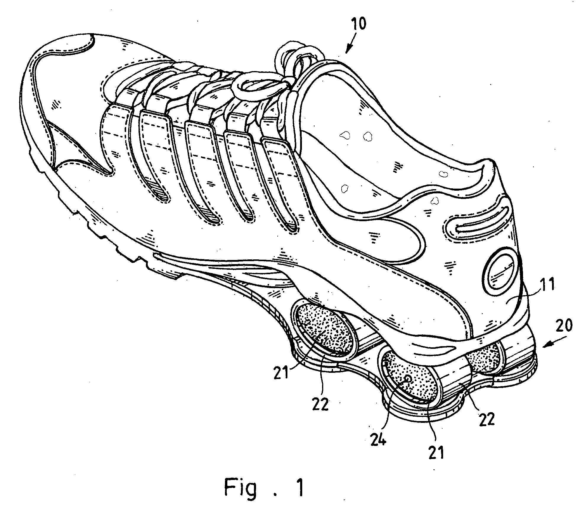
[0024] Referring to the drawings and initially to FIGS. 1-4, one of a pair of elastic shoes in accordance with the preferred embodiment of the present invention comprises a shoe body 10 having a heel portion 11, and an elastic mechanism 20 mounted on the heel portion 11 of the shoe body 10 to provide an elastic shock-absorbing effect to the shoe body 10.

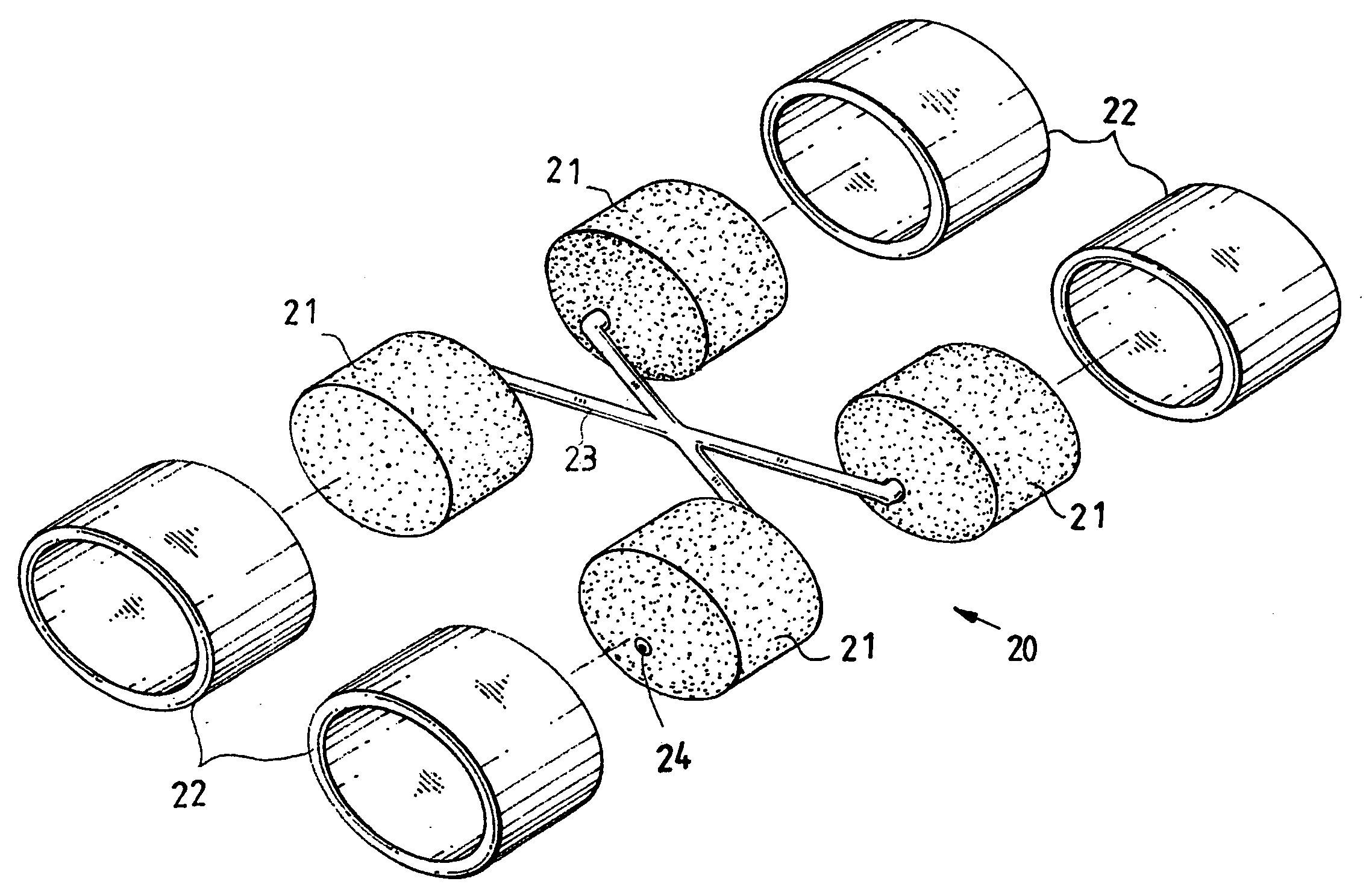
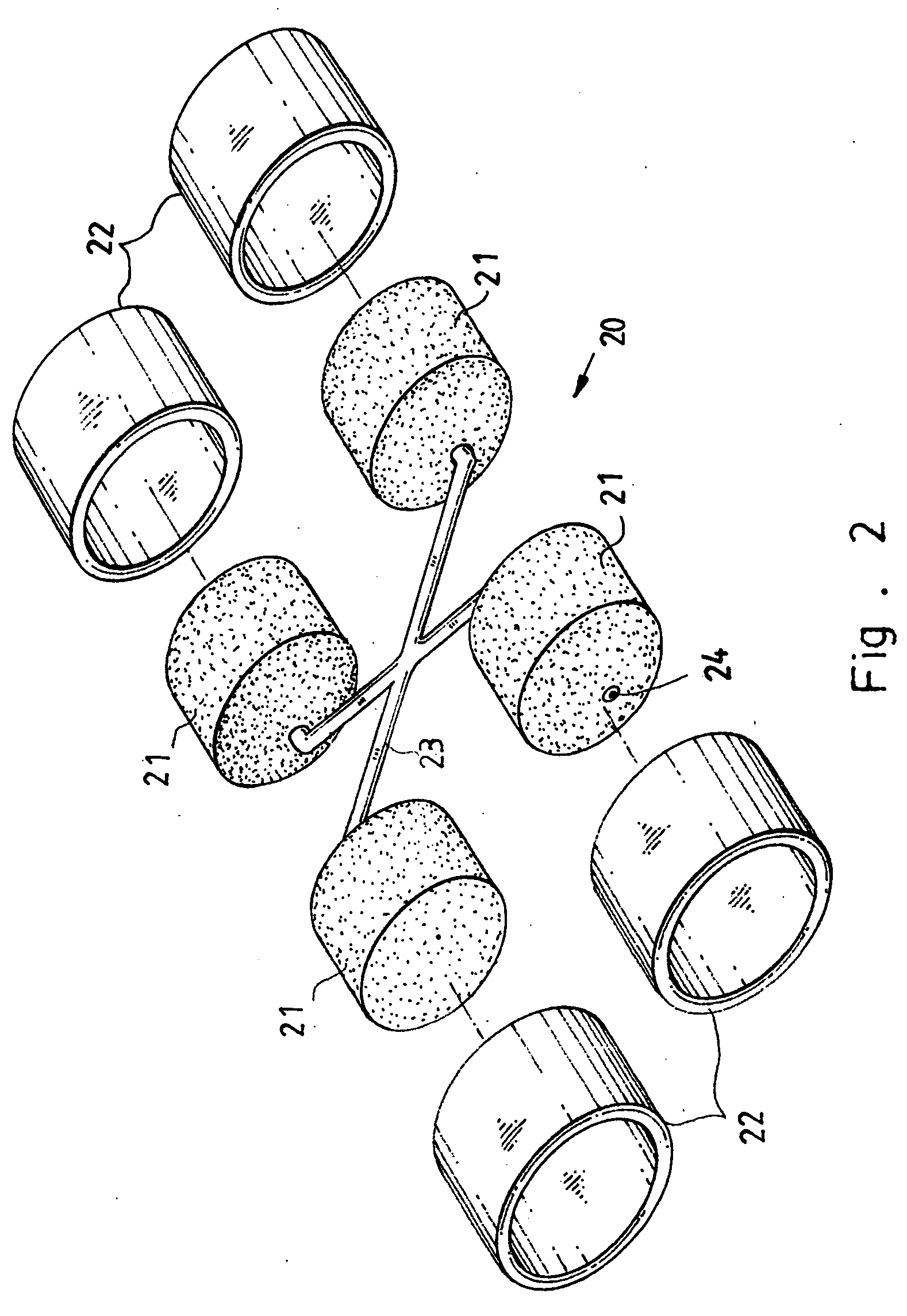
[0025] The elastic mechanism 20 includes a plurality of air cells 21, and a plurality of plastic sleeves 22 each mounted around a periphery of a respective one of the air cells 21. In the preferred embodiment of the present invention, the elastic mechanism 20 includes four air cells 21 and four plastic sleeves 22.

[0026] The air cells 21 are arranged symmetrically and connected with each other by a connecting pipe 23. The connecting pipe 23 has a substantially X-shaped cross-sectional profile.

[0027] Each of the plastic sleeves 22 has a relatively higher elasticity. Each of the plastic sleeves 22 is a hollow body and has a substanti...


PUM


Abstract

The present invention disclosed one of a pair of elastic shoes including a shoe body having a heel portion, and an elastic mechanism mounted on the heel portion of the shoe body. The elastic mechanism includes a plurality of air cells, and a plurality of plastic sleeves. The relatively higher elastic plastic sleeves are mounted around the air cells to produce a restoring force instantaneously when being subjected to the pressure, so that the elastic mechanism has an excellent resilience. Thus, the elastic shoe has excellent elasticity and shock-absorbing effect to provide a comfortable sensation to a user.

Description

BACKGROUND OF THE INVENTION [0001] 1. Field of the Invention [0002] The present invention relates to one of a pair of elastic shoes, and more particularly to an elastic shoe having excellent shock-absorbing effect to provide a comfortable sensation to a user. [0003] 2. Description of the Related Art [0004] A conventional elastic shoe in accordance with the prior art shown in FIGS. 9 and 10 comprises a shoe body 30 having a heel portion 31, and an elastic mechanism 40 mounted on the heel portion 31 of the shoe body 30 to provide an elastic shock-absorbing effect to the shoe body 30. The elastic mechanism 40 includes a plurality of elastic posts 41 each having an inside formed with a through hole 411. However, the elastic posts 41 cannot produce a restoring force instantaneously when being subjected to a pressure, so that the shock-absorbing effect of the elastic mechanism is limited greatly, thereby easily causing an uncomfortable sensation to a user. [0005] The closest prior art ref...

Claims


Application Information

Patent Timeline
IPC IPC(8): A43B13/18A43B13/20
CPCA43B3/0052A43B13/20A43B13/181
Inventor CHANG, KUEI-LIN
Owner CHANG KUEI LIN
Why Eureka
Try Eureka