Method for measuring multiple parameters of a signal transmitted by a signal generator

a signal generator and signal measurement technology, applied in the field of calibration and testing of transmitters, can solve problems such as increasing the overall test tim

Active Publication Date: 2007-02-15
LITEPOINT
View PDF4 Cites 91 Cited by
  • Summary
  • Abstract
  • Description
  • Claims
  • Application Information

AI Technical Summary

Benefits of technology

[0007] A method is disclosed for measuring one or more parameters of a signal generated by a signal generator. The method employs capturing and analyzing a train of data packets or other forms of signals from a single transmission to obtain measured values for the one or more parameters. The obtained measured values may be used in valuing a calibration of a signal generator or in verifying the already calibrated values of the signal generator. In accordance with a preferred embodiment, the train of data packets contains packets having different properties.
[0008] In one embodiment, a method is provided for measuring one or more properties of an output signal generated by a data packet signal generator. The method includes generating a plurality of data packet signals by the data packet signal generator, a portion of the plurality of data packet signals having at least one property that varies in value over a calibrated range of the data packet signal generator. The portion of the plurality of data packet signals is received from the data packet signal generator for analysis. Measuring the value of the at least one property for the received portion of the plurality of data packet signals produces measured values.
[0009] In another embodiment, a method for measuring one or more properties of an output signal generated by a data packet signal generator is provided. The method includes generating a plurality of data packet signals by varying an output power and data rate of the data packet signals as generated by the data packet signal generator. The plurality of data packet signals are received for analysis. A portion of the received plurality of data packet signals is measured to produce measured values for at least one property of the data packet signals of the portion.

Problems solved by technology

However, testing in such a sequential fashion increases the overall test time.
An additional issue contributing to increased test time for testing transmission equipment and / or receiver equipment is that more modern transmitters and receivers are capable of transmitting and receiving data packet signals at multiple frequencies or data rates.

Method used


Image

  • Method for measuring multiple parameters of a signal transmitted by a signal generator
  • Method for measuring multiple parameters of a signal transmitted by a signal generator
  • Method for measuring multiple parameters of a signal transmitted by a signal generator

Examples


Embodiment Construction

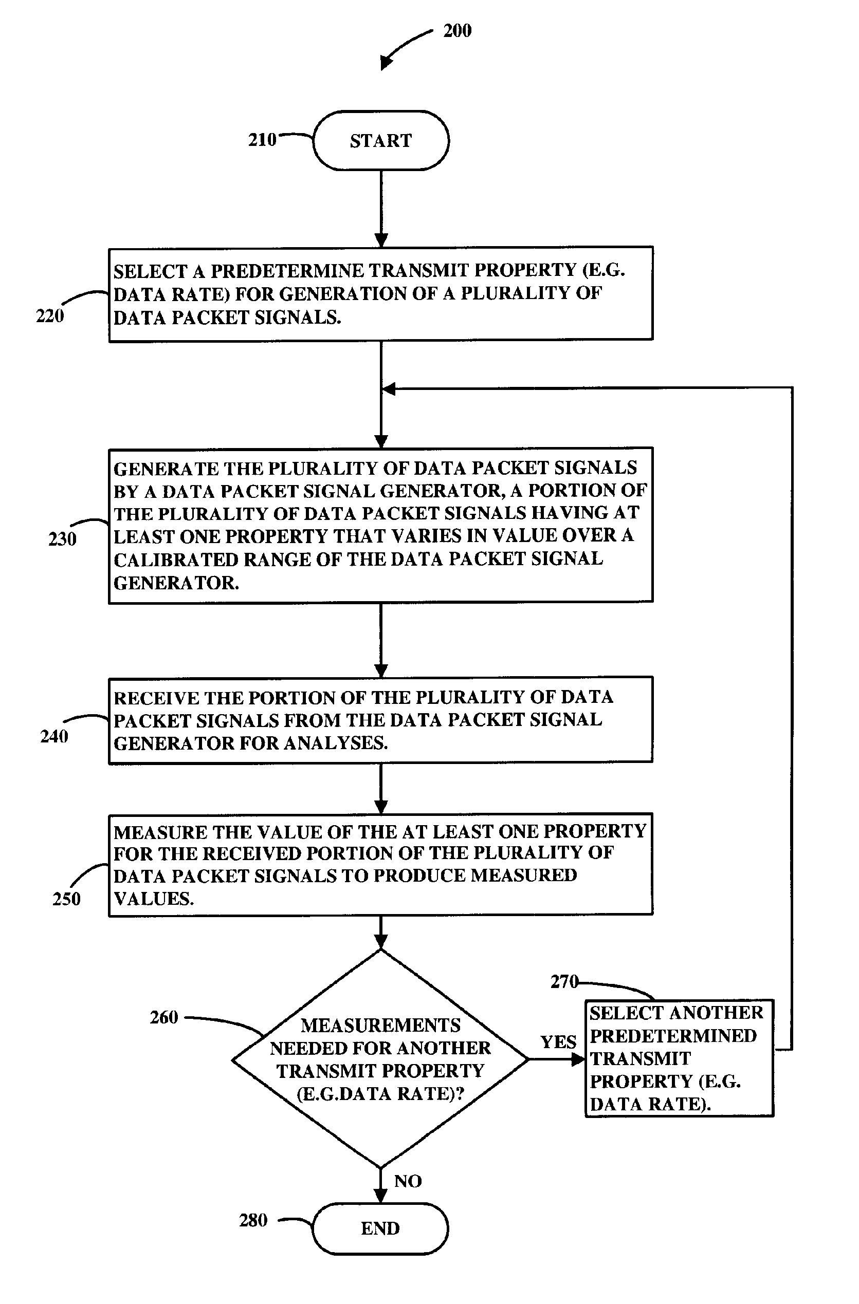
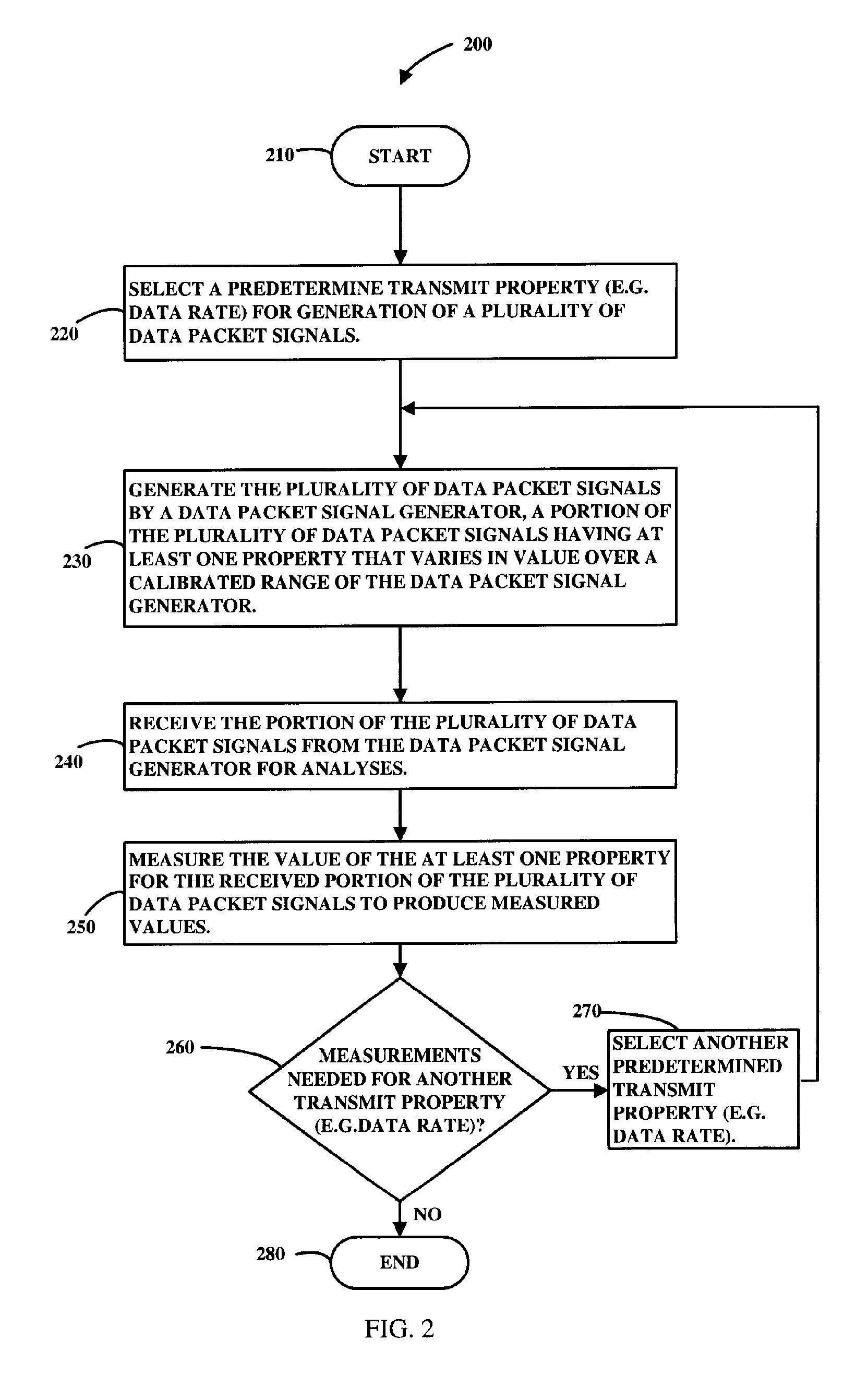
[0019] In the following discussion, for purposes of consistency and simplicity of examples, the generated transmit signal is generally described in terms of data packet signals. However, in accordance with the presently claimed invention, the data signals need not necessarily be in the form of packet data. Alternatively, the generated transmit signals could be in other commonly used forms, such as continuous wave (CW) signals, which represent or otherwise correspond to the specific data, controls, parameters or characteristics sought to be measured, controlled, monitored or tested.

[0020] Additionally, the following discussion uses EVM as an example of a measure of signal quality. However, it should be understood that other measures of transmission signal quality can also be used in accordance with the presently claimed invention. For example, one may analyze the quality of a signal where multiple transmitters with different forms of modulation produce a combined signal, e.g., in a ...


PUM


Abstract

A method is disclosed for measuring one or more parameters of a signal generated by a signal generator. The method employs capturing and analyzing a train of data packets or other forms of signals from a single transmission to obtain measured values for the one or more parameters. The obtained measured values may be used in valuing a calibration of a signal generator or in verifying the already calibrated values of the signal generator. In accordance with a preferred embodiment, the train of data packets contains packets having different properties.

Description

BACKGROUND OF THE INVENTION [0001] The present invention relates generally to calibration and testing of a transmitter (referred to herein as a data signal generator) and / or a receiver (referred to herein as a data signal receiver) and more particularly, to reduction in test time for performing the measurement of one or more parameters or properties of transmitted signals transmitted by a device under test (DUT) and / or received by a DUT. [0002] An electronic transmitter and / or receiver forms a basic component in mobile cell phones, wireless personal computers (PCs), and wireless devices in general. Typically, a wireless device is tested for acceptable performance before leaving production facilities. For example, part of the testing of the wireless device may include measuring quality parameters associated with a transmitted signal that is output by the wireless device and / or reception capabilities of the transmitted signal by the receiver of the wireless device. [0003] Traditionall...

Claims


Application Information

Patent Timeline
Patent Type & Authority Applications(United States)
IPC IPC(8): H04B17/00
CPCH04B17/21H04B17/00
Inventor OLGAARD, CHRISTIAN
Owner LITEPOINT
Why Eureka
Try Eureka