Adaptive compression and decompression of bandlimited signals

a bandlimited signal and compression technology, applied in the field of compression and decompression of sampled analog signals, can solve the problems of inability to operate at increasingly fast sampling rates, inability to meet the needs of non-standard metrics, and existing lossy compression, so as to achieve less bandwidth and storage, and higher sampling rates. , the effect of increasing the sampling ra

Inactive Publication Date: 2006-03-07
TAHOE RES LTD
View PDF11 Cites 205 Cited by
  • Summary
  • Abstract
  • Description
  • Claims
  • Application Information

AI Technical Summary

Benefits of technology

[0073]There is an increasing need for algorithms that compress and decompress sampled analog signals in real time, where the compressed representation requires significantly less bandwidth and storage than the original sampled data signal. It is appreciated that the compression and decompression methods of the present invention fulfill these requirements. Furthermore, the present invention scales with sampling rates, i.e. as faster A / D and D / A converters are developed, the present invention scales to process signals from such improved converters. A particular implementation of the present invention, utilizing parallel processing for compression or decompression, offers scalability to higher sampling rates by using two or more compressors, or two or more decompressor, working together to compress a sampled input signal at increasingly higher sampling rates. The present invention requires only a moderate amount of processing resources: programmable logic elements of a field-programmable gate array [FPGA], gates of an application-specific integrated circuit [ASIC], or MIPS of a programmable processor, such as a DSP or microprocessor. Thus the present invention's compression and decompression operations enable sampled data acquisition applications requiring real-time compression, as well as sampled signal generation applications requiring real-time decompression.
[0085]k) for enhanced D / A converters, to provide a method of decompressing the compressed input of D / A converters that lowers the data rate or number of pins at the digital input of such enhanced D / A converters,
[0086]Further objects and advantages of my invention will become apparent from a consideration of the drawings and ensuing description.
[0087]In a sampled data compression and sampled data decompression system, the present invention uses one or more preprocessors to improve the compression performance of one or more compressors. The preprocessor optionally increases the redundancy, lowers the bandwidth, changes the sampling rate, or decreases the noise of an input signal to be compressed, so that the compression rate at the output of the compressor is improved. During decompression, a decompressor recreates the original preprocessor output signal, and a postprocessor reverses the operations performed by the preprocessor in order to recreate the sampled input signal originally provided as input to the preprocessor. Preprocessor and compressor operations, as well as decompressor and postprocessor operations, are simple mathematical functions suitable for hardware implementation in ASICs or FPGAs, or (at lower sampling rates) on programmable DSPs or microprocessors. The simplicity of the present invention's preprocessor, compressor, decompressor, and postprocessor enables real-time compression and decompression of analog signals at high sampling rates. Specific examples of applications in test and measurement, data conversion, and data transfer across busses, cables, and networks are developed to demonstrate the improved performance achieved when these applications integrate certain embodiments of the present invention.

Problems solved by technology

To summarize, existing lossy compression methods developed for signals that are intended for human listening or viewing suffer from the following drawbacks when applied to a broader class of wideband, bandlimited sampled high-speed analog signals:a) they incorrectly use assumptions about signal characteristics that are not applicable,b) they cannot operate at increasingly fast sampling rates due to their complexity,c) they cannot operate effectively as the center frequency, bandwidth, or noise floor (SNR) of the input signal varies,d) they minimize distortion metrics that reflect known limitations of human hearing and vision, but such metrics are not appropriate for non-audible, non-visual signals,e) they do not inform users when the distortions introduced during lossy compression will be noticeable.

Method used


Image

  • Adaptive compression and decompression of bandlimited signals
  • Adaptive compression and decompression of bandlimited signals
  • Adaptive compression and decompression of bandlimited signals

Examples


Embodiment Construction

[0140]An efficient compression and decompression method for sampled high-speed analog signals is described. In the following description, numerous specific details are presented in order to provide a thorough understanding of the present invention. It will be obvious, however, to one skilled in the art that the present invention may be practiced without these specific details. In other instances, well-known methods are not described in detail in order not to unnecessarily obscure the description of the present invention.

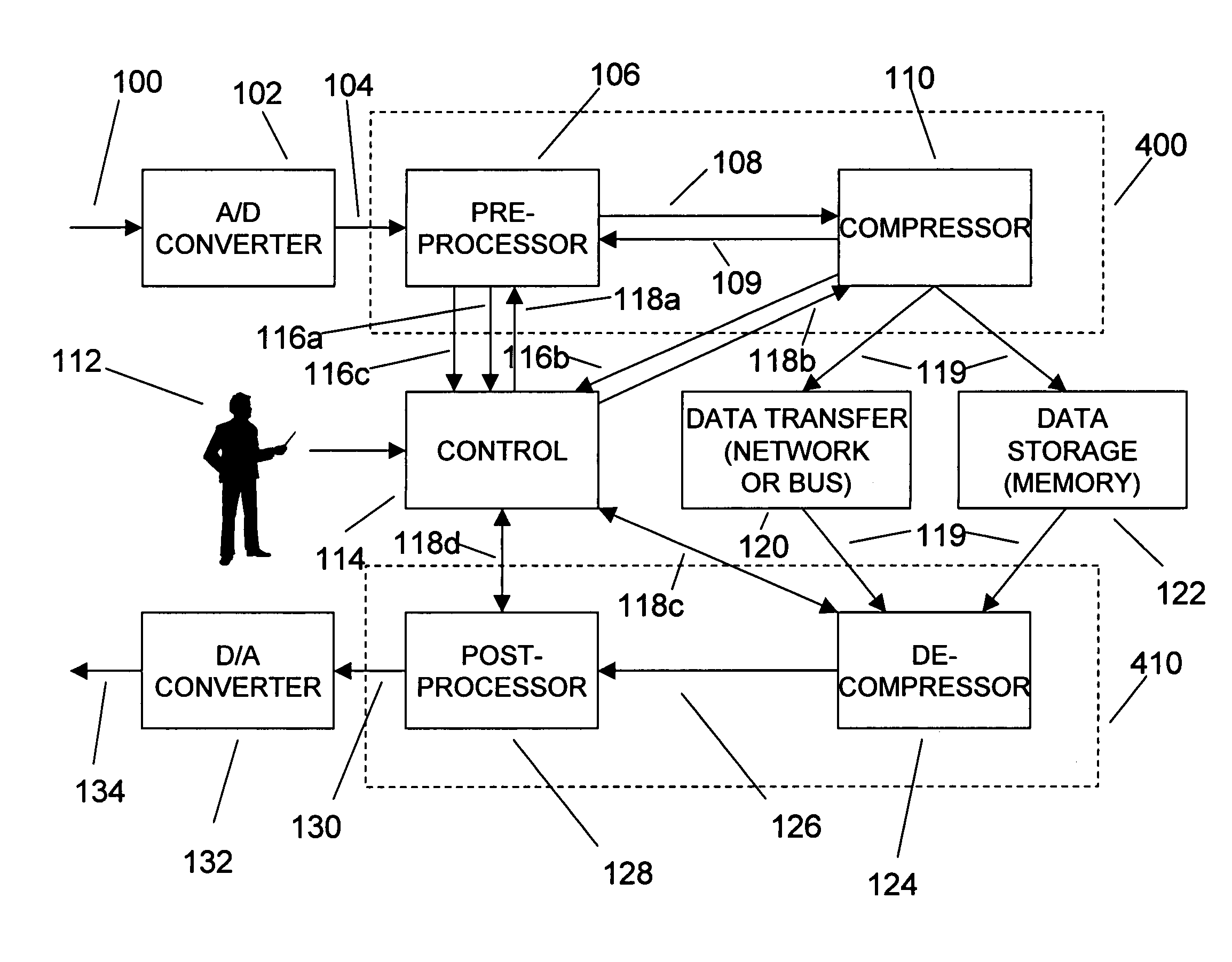
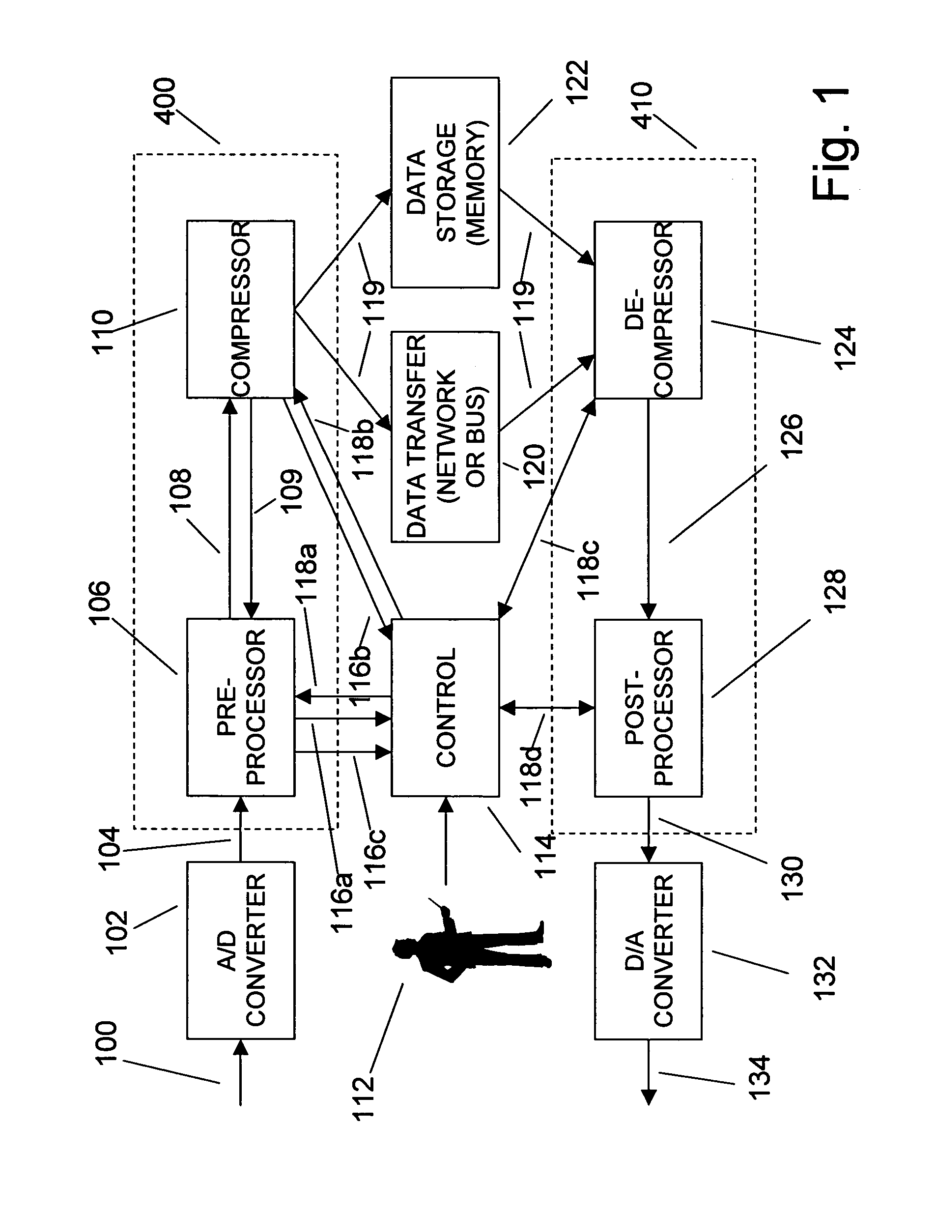
[0141]FIG. 1 provides an overview of the present invention, in the context of an analog input and an analog output system. The purpose of a compression subsystem 400 is to reduce the sampled data requirements between an analog-to-digital (A / D) converter 102 and a data storage logic 122, or between A / D converter 102 and a data transfer logic 120. The purpose of a decompression subsystem 410 is to reduce the sampled data requirements between data storage logic 122 and ...


PUM


Abstract

An efficient method for compressing sampled analog signals in real time, without loss, or at a user-specified rate or distortion level, is described. The present invention is particularly effective for compressing and decompressing high-speed, bandlimited analog signals that are not appropriately or effectively compressed by prior art speech, audio, image, and video compression algorithms due to various limitations of such prior art compression solutions. The present invention's preprocessor apparatus measures one or more signal parameters and, under program control, appropriately modifies the preprocessor input signal to create one or more preprocessor output signals that are more effectively compressed by a follow-on compressor. In many instances, the follow-on compressor operates most effectively when its input signal is at baseband. The compressor creates a stream of compressed data tokens and compression control parameters that represent the original sampled input signal using fewer bits. The decompression subsystem uses a decompressor to decompress the stream of compressed data tokens and compression control parameters. After decompression, the decompressor output signal is processed by a post-processor, which reverses the operations of the preprocessor during compression, generating a postprocessed signal that exactly matches (during lossless compression) or approximates (during lossy compression) the original sampled input signal. Parallel processing implementations of both the compression and decompression subsystems are described that can operate at higher sampling rates when compared to the sampling rates of a single compression or decompression subsystem. In addition to providing the benefits of real-time compression and decompression to a new, general class of sampled data users who previously could not obtain benefits from compression, the present invention also enhances the performance of test and measurement equipment (oscilloscopes, signal generators, spectrum analyzers, logic analyzers, etc.), busses and networks carrying sampled data, and data converters (A/D and D/A converters).

Description

1.0 BACKGROUND—FIELD OF INVENTION[0001]This invention relates to the compression and decompression of sampled analog signals, and especially to efficient lossless and lossy compression and decompression solutions for systems processing high-speed, bandlimited analog signals.2.0 BACKGROUND[0002]A desirable goal in sampled data systems is to minimize the representation of the signal being sampled. In minimizing the representation, two related results are achieved:[0003]a) the amount of storage required for the signal is minimized, and[0004]b) the bandwidth required for transmitting the signal is decreased.By decreasing storage and bandwidth requirements, significant cost savings are also realized.[0005]Recently, the rapid increase in the amount of sampled data, sampled at ever-increasing sampling rates, has also increased the potential benefits of minimizing the digital representation of analog signals. Sampled analog signals consume significant bandwidth and memory during acquisition...

Claims


Application Information

Patent Timeline
Patent Type & Authority Patents(United States)
IPC IPC(8): H03M7/30
CPCH04N1/413
Inventor WEGENER, ALBERT W.
Owner TAHOE RES LTD
Why Eureka
Try Eureka