Two-arm belt tensioner

a belt tensioner and two-arm technology, applied in the direction of belt/chain/gearing, machine/engine, belt/chain/gearing, etc., can solve the problems of unsuitability for highly compact combustion engines, excessive bulk, and inconvenient production, so as to achieve high compactness, reliable and efficient, and cheap

Active Publication Date: 2007-02-15
DAYCO EURO +1
View PDF6 Cites 59 Cited by
  • Summary
  • Abstract
  • Description
  • Claims
  • Application Information

AI Technical Summary

Benefits of technology

The technical effect of this patent is to offer a cost-effective and practical solution for tightening up two arms with a belt. This device is small, trustworthy, effective, and can be easily produced.

Problems solved by technology

The technical problem addressed in this patent text relates to finding better ways to control belt tension in small combustion engines that use reversible electric machines. Current methods with two-arm belt tensioners can be too big for these engines and may not work well with smaller springs.

Method used


Image

  • Two-arm belt tensioner
  • Two-arm belt tensioner
  • Two-arm belt tensioner

Examples


Embodiment Construction

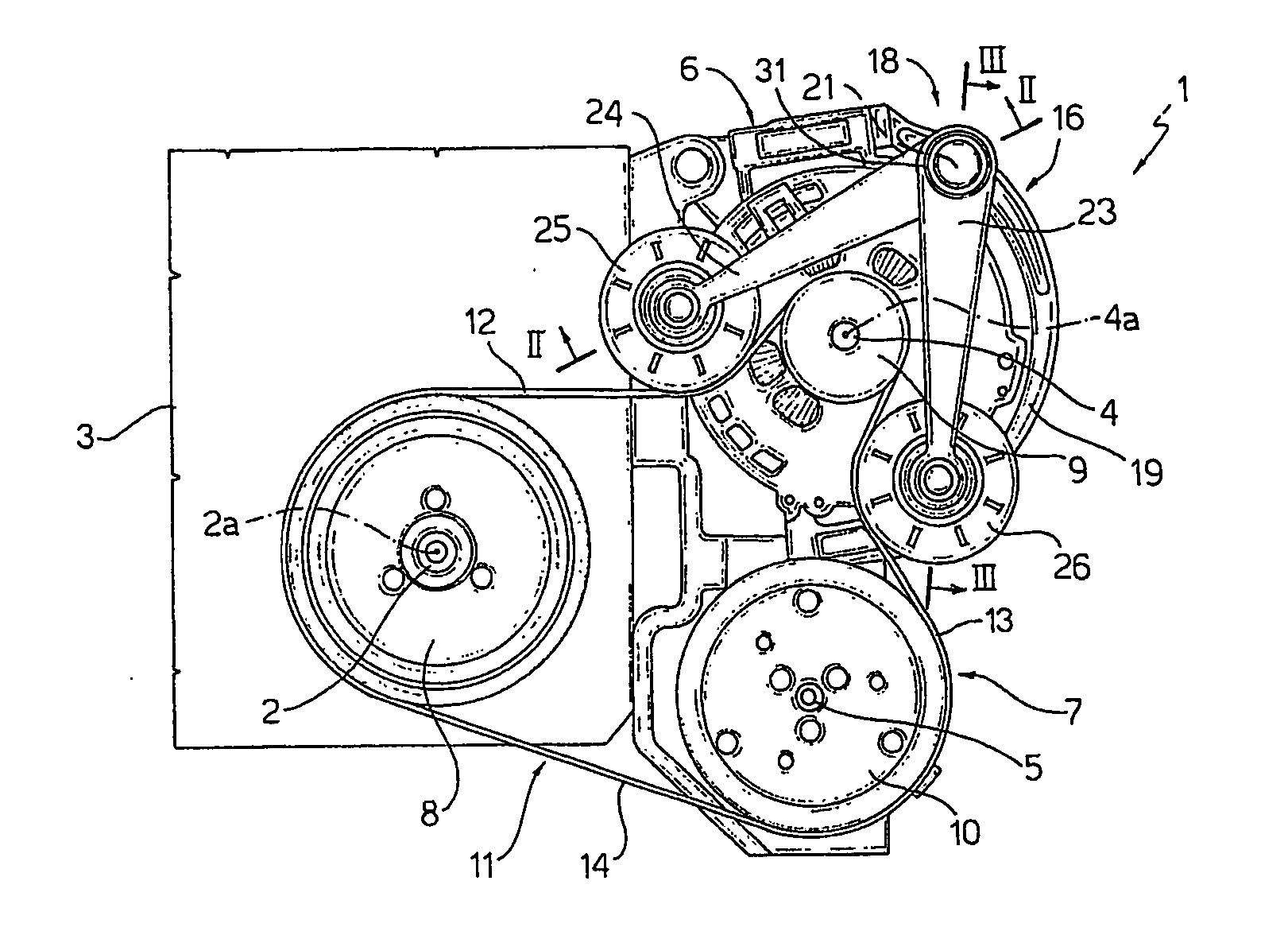
[0013] Number 1 in FIG. 1 indicates as a whole a belt drive for connecting the output shaft 2 of an internal combustion engine 3 to the shaft 4 of a reversible electric machine 6, i.e. capable of operating as a current generator or motor, and to a shaft 5 of an auxiliary member 7, e.g. an air-conditioning system compressor.

[0014] More specifically, drive 1 comprises a pulley 8 fitted to shaft 2 of the engine; a pulley 9 integral with shaft 4 of the electric machine; and a pulley 10 integral with shaft 5 of auxiliary member 7. Pulleys 8, 9 and 10 are wound with an endless belt 11, which has a first branch 12 extending between pulleys 8 and 9, a second branch 13 extending between pulleys 9 and 10, and a third branch 14 extending between pulleys 8 and 10. Belt 11 is conveniently a poly-V type, and pulleys 8, 9 and 10 each have a corresponding work profile (not shown) with multiple grooves.

[0015] With reference to FIG. 1, drive 1 also comprises a two-arm belt tensioner 16 cooperating ...


PUM


Abstract

In a belt drive of an internal combustion engine, a two-arm belt tensioner has a fixed tubular supporting portion; a first and a second arm fitted to the tubular supporting portion to rotate about a common hinge axis, and supporting respective idle wheels cooperating with respective branches of the drive belt; and an elastic device for forcing the arms towards each other; the elastic device having a torsionally elastic elongated member extending through the tubular supporting portion, coaxially with the hinge axis, and having respective opposite end portions projecting outwards of the tubular supporting portion; the end portions being fitted with respective end caps, one of which is fitted directly with one of the arms, and houses one end, connected integrally to the other cap, of the other arm.

Description


Claims


Application Information

Patent Timeline
Owner DAYCO EURO
Why Eureka
Try Eureka