Foldable pawl and ratchet assembly

a technology of ratchet and pawl, which is applied in the field of folding pawl and ratchet assembly of furniture, can solve the problems of increased manufacturing time and cost of furniture, ratcheting or clicking noise, and the pawl arm and locking tip may not provide the optimum angle for engagement, so as to reduce sliding contact friction, reduce manufacturing time and cost, and facilitate disengagement

Inactive Publication Date: 2007-02-22
LA-Z-BOY
View PDF10 Cites 19 Cited by
  • Summary
  • Abstract
  • Description
  • Claims
  • Application Information

AI Technical Summary

Benefits of technology

[0012] A foldable pawl and ratchet assembly of the present invention provides several advantages. By rotatably coupling a pawl lever to a pawl link, the pawl lever can more easily disengage from an engaged position between teeth of a ratchet, to allow continued backward rotation of a furniture member. The use of a polymeric material for the pawl lever provides a quieter operation as the pawl lever rotates past the teeth both between engaged positions and when pawl lever is released. The polymeric material also reduces the sliding contact friction between the pawl lever and teeth. A biasing element continuously biases pawl lever toward a contact position with pawl link which promotes engagement of a ratchet engaging end of pawl lever with teeth to prevent forward or return motion of the furniture member until the operator manually disengages the leg rest operating mechanism and pawl assembly together.

Problems solved by technology

Known mechanisms commonly include a large number of moving parts that tends to increase the manufacturing time and costs associated with the furniture.
The common one-piece construction of the pawl arm and locking tip may not provide the optimum angle for engagement with the teeth of the ratchet sector.
As the furniture member rocks backward when the leg rest is moved between the successive positions, a noticeable ratcheting or clicking noise occurs as the pawl engages successive teeth of the ratchet.
This noise results at least in part because common pawl members and ratchet sectors are both created of metal material which transmit contact noise.

Method used


Image

  • Foldable pawl and ratchet assembly
  • Foldable pawl and ratchet assembly
  • Foldable pawl and ratchet assembly

Examples


Embodiment Construction

[0033] The following description of some preferred aspects of the present invention is merely exemplary in nature and is in no way intended to limit the invention, its application, or uses.

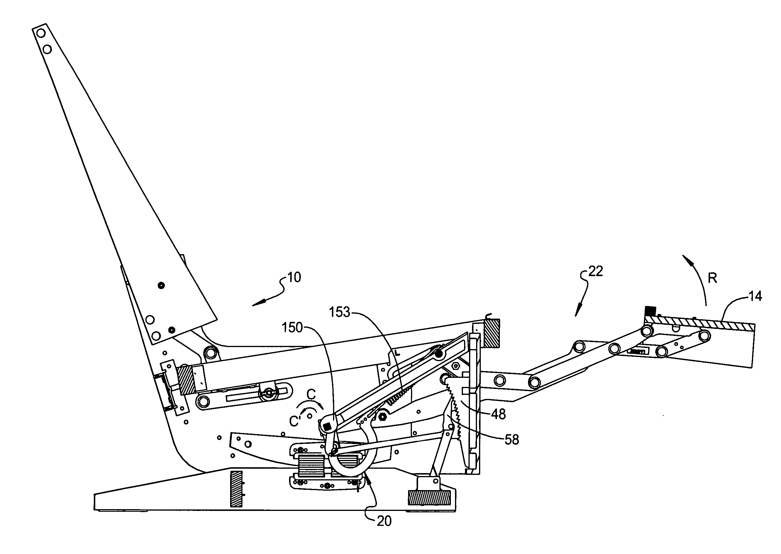
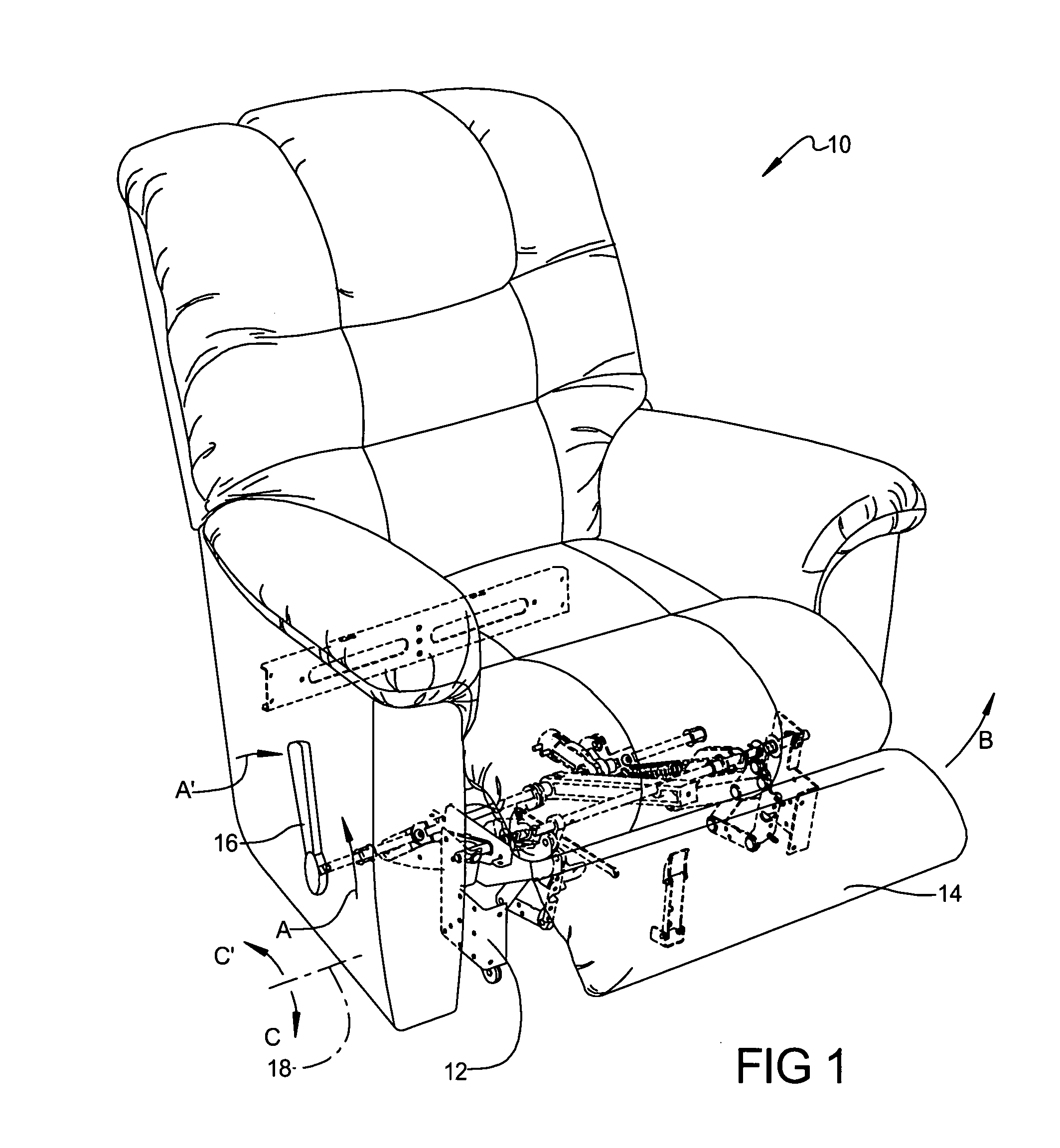
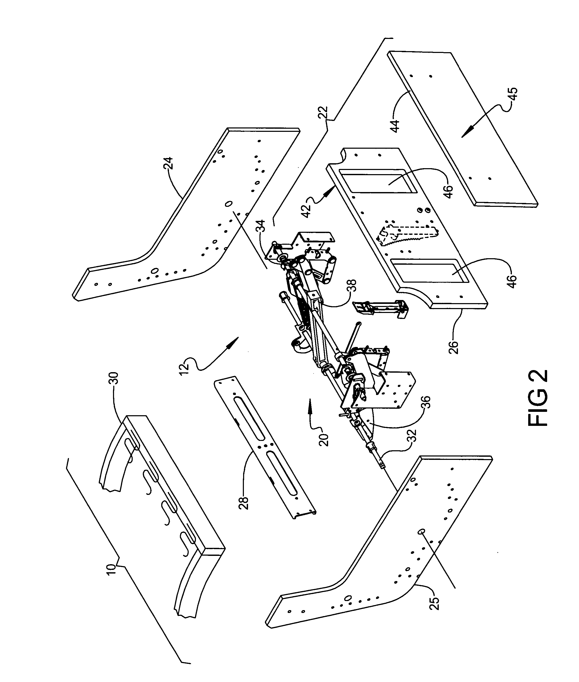
[0034] With particular reference now to the drawings, in accordance with the teachings of the present invention and referring generally to FIG. 1, a furniture member 10 such as a rocking, reclining chair includes an actuation mechanism 12 for use in single or multi-person furniture members 10. In the aspect shown, furniture member 10 is a chair, however, the invention is not limited to chairs. Furniture member 10 can be any of a plurality of furniture members, including, but not limited to chairs, sofas and / or loveseats. Furniture member 10 and actuation mechanism 12 in the Figures herein are further shown representing a rocking configuration. Actuation mechanism 12 controls the position of a leg rest 14 between a stowed position (shown in phantom) and an extended position (partially shown) by op...


PUM


Abstract

A ratchet device for a rocking furniture member has a plurality of structural elements. The ratchet device temporarily retains the furniture member in multiple engaged positions and includes: a pawl assembly having a pawl link rotatably connected to a first structural element; a plastic pawl lever rotatably connected to the pawl link; a first biasing element positioned between the pawl link and the pawl lever which biases the pawl lever toward a contact position with the pawl link; and a U-shaped bracket rotatably coupled to the pawl link and fixed to the first structural element. A ratchet having engagement teeth is fixed to a second structural element and located with the engagement teeth in a rotational path of the pawl lever. A second biasing element connected between the pawl link and the U-shaped bracket biases the pawl lever to engage the ratchet teeth.

Description

FIELD OF THE INVENTION [0001] The present invention relates in general to furniture member operating mechanisms and more specifically to a device and method for operating a furniture leg rest assembly. BACKGROUND OF THE INVENTION [0002] Conventionally, reclining articles of furniture (i.e., chairs, sofas, loveseats, and the like) require a mechanism to bias a leg rest assembly in the extended and stowed positions. Known mechanisms commonly include a large number of moving parts that tends to increase the manufacturing time and costs associated with the furniture. [0003] Most rocking chairs typically include an upholstered chair frame supported from a stationary base assembly in a manner permitting the chair frame to “rock” freely with respect to the base assembly. In order to provide enhanced comfort and convenience, many rocking chairs also include a “reclinable” seat assembly and / or an “extensible” leg rest assembly. For example, combination platform rocking / reclining chairs, as d...

Claims


Application Information

Patent Timeline
Patent Type & Authority Applications(United States)
IPC IPC(8): A47C1/02
CPCA47C1/0345
Inventor LAPOINTE, LARRY P.MARSHALL, RICHARD E.
Owner LA-Z-BOY
Why Eureka
Try Eureka