Single cell module system

a single cell module and module technology, applied in the field of single cell module system, can solve the problems of premature failure of the cell, unprotected cell, and direct cell carrying in the module, and achieve the effect of good airflow for cooling

Inactive Publication Date: 2007-02-22
EAST PENN MFG CO INC
View PDF1 Cites 17 Cited by
  • Summary
  • Abstract
  • Description
  • Claims
  • Application Information

AI Technical Summary

Benefits of technology

[0010] A further object of the invention is to provide a system that is simple and inexpensive to construct, but sturdy and reliable in use.
[0013] A further object of the invention is to provide a system, which provides good airflow for cooling the battery cells.

Problems solved by technology

While this structure is satisfactory, the cells are carried directly in the module and are not protected during installation and removal.
This practice can lead to stress on the posts, which can lead to acid leaks through the post, or damage to the cover leading to premature failure of the cell.
These systems are typically used in the communications industry, which requires uninterruptible power.

Method used


Image

  • Single cell module system
  • Single cell module system
  • Single cell module system

Examples


Embodiment Construction

[0027] When referring to the preferred embodiment, certain terminology will be utilized for the sake of clarity. Use of such terminology is intended to encompass not only the described embodiment, but also technical equivalents, which operate and function in substantially the same way to bring about the same result.

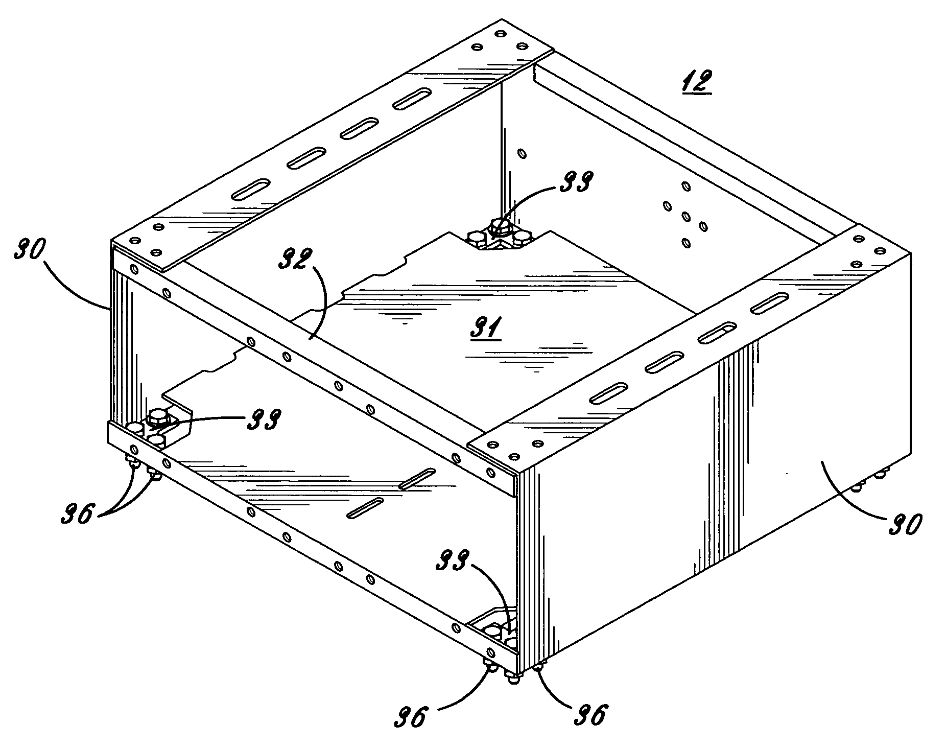
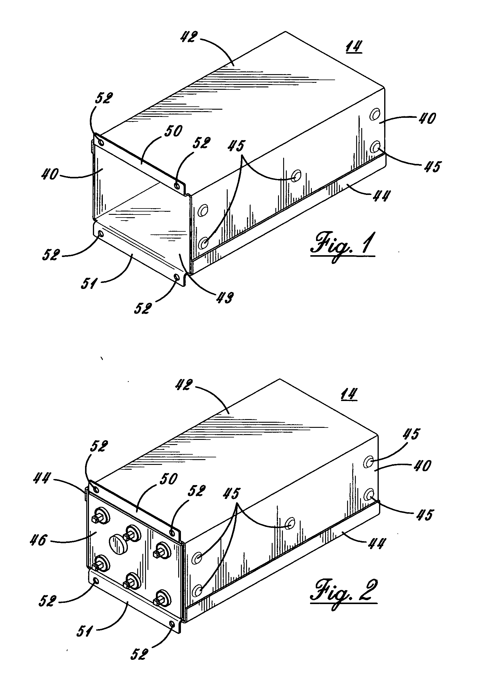
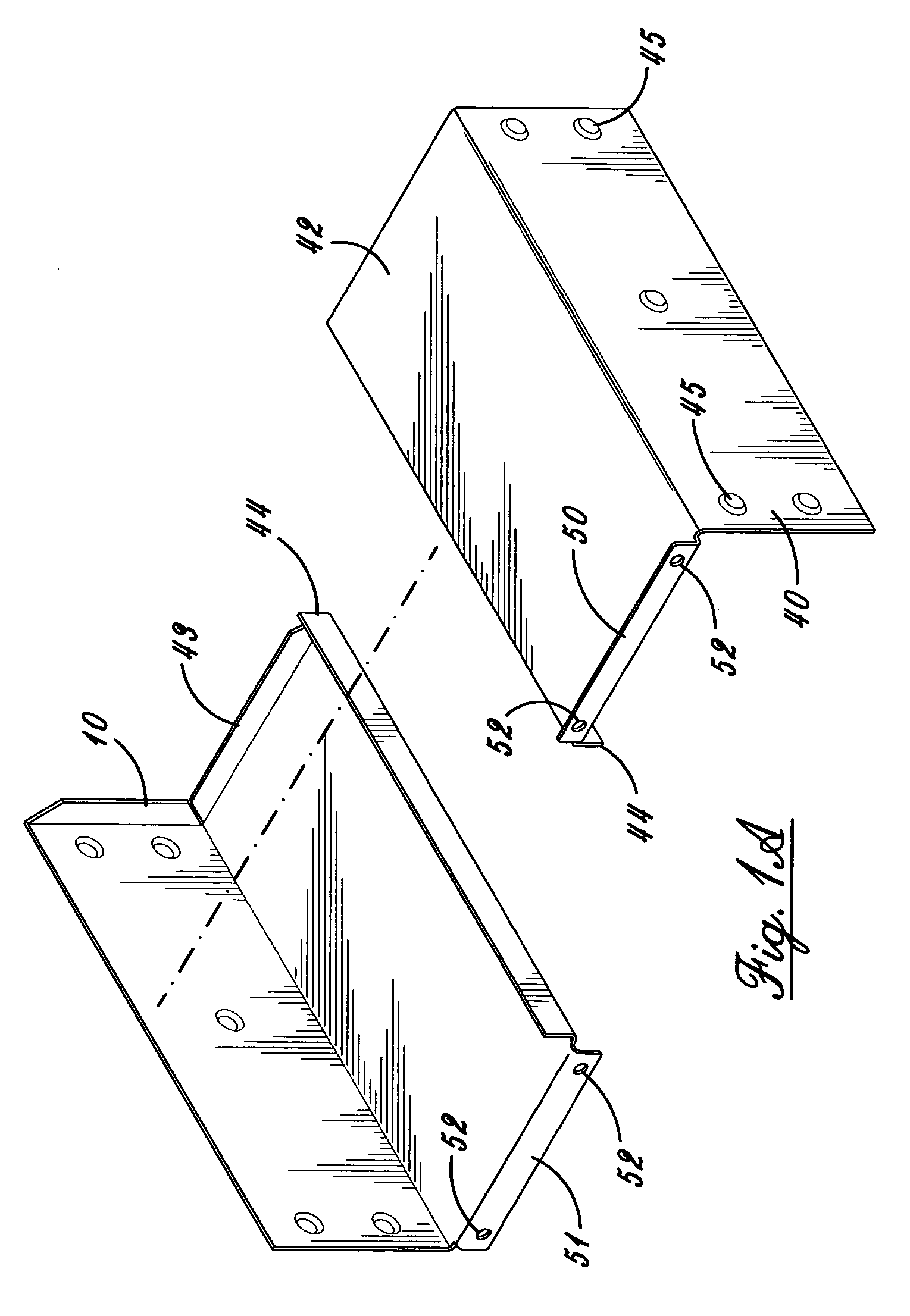
[0028] Preferring now more particularly to the drawings and FIGS. 1-7, the single cell module system 10 is illustrated therein. The system 10 includes a mounting base 11, a module 12, and a plurality of individual cell sleeves 14, to be described.

[0029] The mounting base 11 as shown in FIGS. 4 and 4A is of symmetric square configuration preferably constructed of metal stampings, with a rear channel 16, front channel 17, and connecting side channels 18, with support plates 19 under channels 18. The front and rear channels 17 and 16 are of open square configuration, and the side channels 18 include U-shaped plates 20, which reinforce the channels 18, and L-shaped plates 2...


PUM

PropertyMeasurementUnit
weightsaaaaaaaaaa
weightsaaaaaaaaaa
weightaaaaaaaaaa

Abstract

A single cell module system, which has a mounting, base a module attached to the base, and at least one sleeve which fits into the module and receives a battery cell, with the modules stackable on the base.

Description

FIELD OF THE INVENTION [0001] This invention relates to a single cell module system for lead-acid batteries, which system protects the cell during handling, permitting the cell to be installed or removed from the module without contacting the cell. DESCRIPTION OF THE PRIOR ART [0002] In the prior art, it has been known to provide modular cell tray assemblies, which contain a plurality of cells, which are connected together to form batteries for use as stand by, or uninterruptible power supplies, for use by computer systems, or for other applications where uninterruptible power supplies are required. Such systems typically use a plurality of sealed lead-acid cells, which cells are connected together in series, or parallel, to form batteries, which provide the power source. [0003] Such assemblies are known in the art, such as shown in the U.S. Patent to Sherwood, No. U.S. Pat. No. 6,451,475 B1, which has a base with a plurality of cell tray assemblies thereon. While this structure is ...

Claims


Application Information

Patent Timeline
Patent Type & Authority Applications(United States)
IPC IPC(8): H01M2/10B65D85/00H01M50/202H01M50/262
CPCH01M2/1072H01M2/1094H01M10/12H01M10/647H01M10/6556H01M10/6561H01M10/627H01M10/613Y02E60/10H01M50/24H01M50/202H01M50/262
Inventor BALASH, GARY M.
Owner EAST PENN MFG CO INC
Why Eureka
Try Eureka