Multiport waveguide device

a waveguide and multi-port technology, applied in the direction of selection arrangements, multiplex system selection arrangements, electrical devices, etc., can solve the problems of waveguide insertion losses, large and bulky existing assemblies, and expensive existing assemblies

Active Publication Date: 2022-07-05
HUGHES NETWORK SYST
View PDF2 Cites 0 Cited by
  • Summary
  • Abstract
  • Description
  • Claims
  • Application Information

AI Technical Summary

Benefits of technology

[0004]The present disclosure provides a multiport waveguide device enabled for the simultaneous reception of multiple incoming RF signals and / or the simultaneous transmission of multiple outgoing RF signals. More specifically, the multiport waveguide device of the present disclosure employs an orthogonal mode transducer (OMT) to integrate two orthogonal polarization signals (one is transmitting and the other is receiving) for the same antenna. The multiport waveguide device can be a 5-port OMT with dual polarization and dual diplexer integration, allowing a radio terminal to take advantage of two orthogonal polarization receiving signals (at the same bandwidth, at the same time), and transmitting one or two orthogonal signals at the same bandwidth to a satellite. The multiport waveguide device further uses a 90 degree waveguide twist to transfer both the receiving orthogonal mode and the transmitting orthogonal mode to be horizontal modes (e.g., transfer an E-plane split to an H-plane split, or vice versa, for high yield split manufacturing), with a minimum E-plane split area, boosting the robustness and consistency of RF performance after assembly. With the disclosed multiport waveguide device, the integration of a transmitting electronic circuit and a receiving electronic circuit can implemented on the same circuit board, minimizing the overall size and reducing production cost. Thus, the multiport waveguide device described herein has a compact design, is simple and inexpensive to construct, achieves high tolerances, does not require electromechanical switching, and enables a single circuit board to be used for all of the receiving and transmitting ports. This structure also enables wide band radio design with low insertion loss.

Problems solved by technology

It has been determined that existing conventional assemblies are costly and not suited for mass production.
Existing assemblies are also typically large and bulky, experience waveguide insertion losses, and / or do not allow a single circuit board to be used for all of the receiving and transmitting ports.

Method used


Image

  • Multiport waveguide device
  • Multiport waveguide device
  • Multiport waveguide device

Examples


Embodiment Construction

[0016]Selected embodiments will now be explained with reference to the drawings. It will be apparent to those skilled in the art from this disclosure that the following descriptions of the embodiments are provided for illustration only and not for the purpose of limiting the invention as defined by the appended claims and their equivalents.

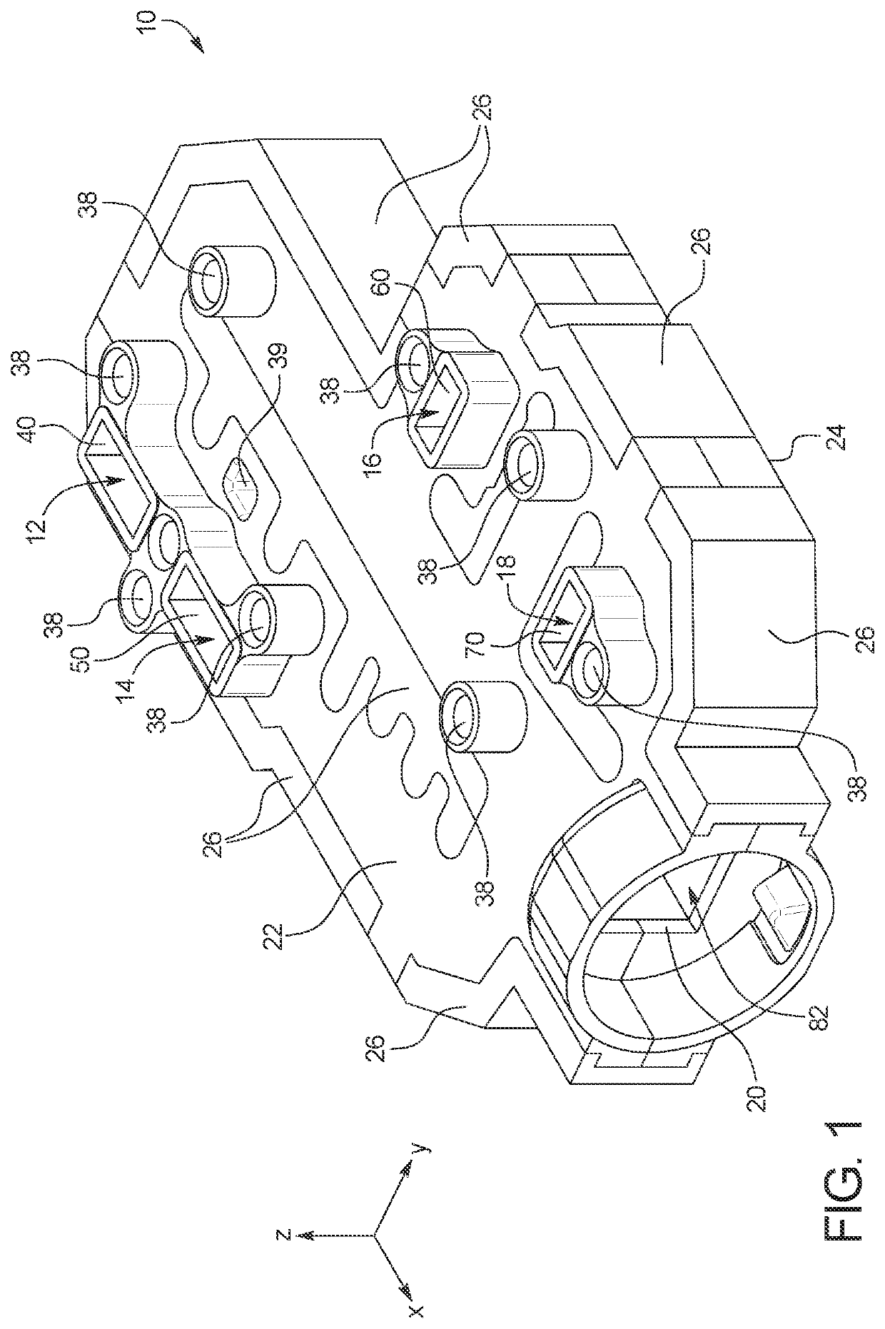
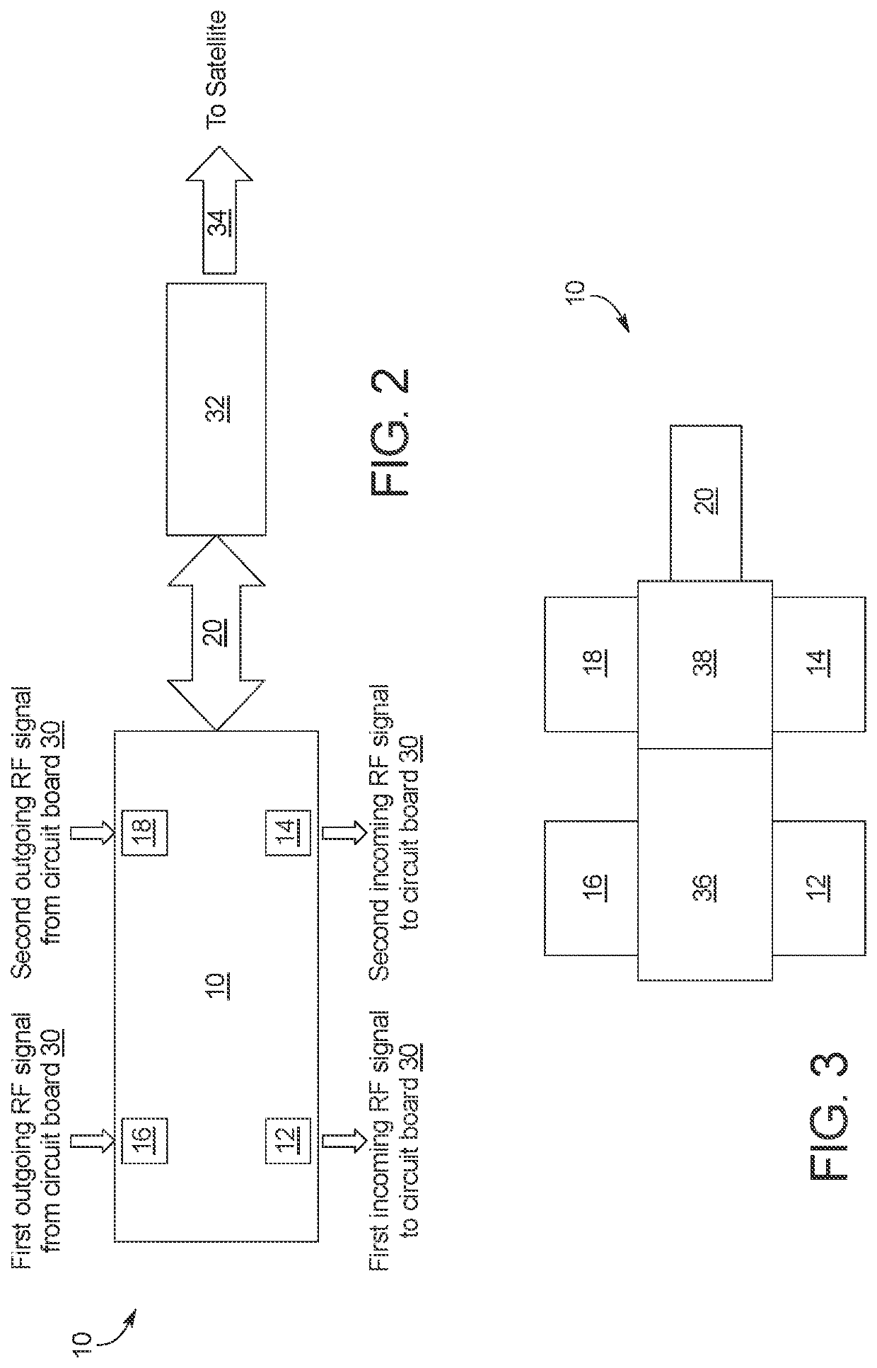
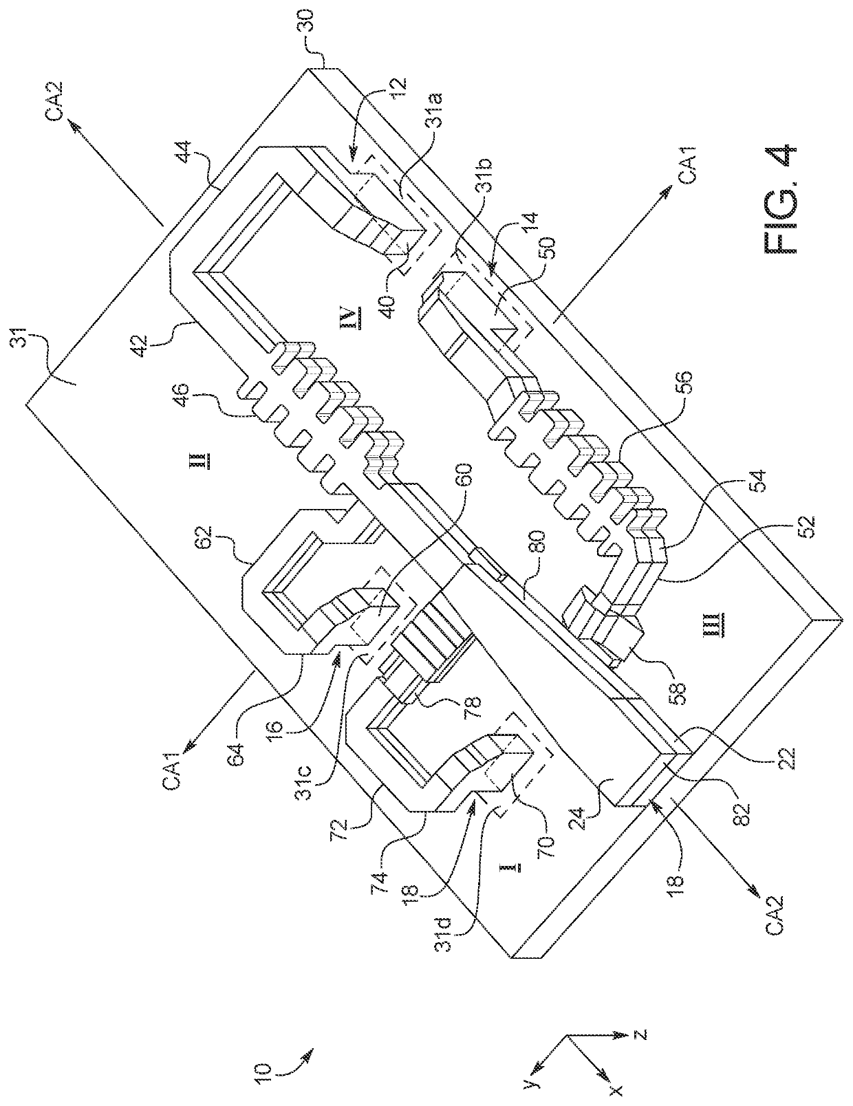
[0017]FIG. 1 illustrates an example embodiment of a multiport waveguide device 10 in accordance with the present disclosure. In the illustrated embodiment, the multiport waveguide device 10 includes a first receiving port structure 12, a second receiving port structure 14, a first transmitting port structure 16, a second transmitting port structure 18, and a common port structure 20. Thus, the multiport waveguide device 10 in the illustrated embodiment is a five-port device. It should be understood by those of ordinary skill in the art from this disclosure, however, that the multiport waveguide device 10 is not limited to five ports and can includ...


PUM


Abstract

A multiport waveguide device is disclosed herein. In an embodiment, a multiport waveguide device includes a first receiving port structure configured to guide a first incoming RF signal, a second receiving port structure configured to guide a second incoming RF signal, a first transmitting port structure configured to guide a first outgoing RF signal, and a second transmitting port structure configured to guide a second outgoing RF signal. The multiport waveguide device also includes common port structure configured to simultaneously guide the first incoming RF signal, the second incoming RF signal, the first outgoing RF signal, and the second outgoing RF signal through a common port.

Description

BACKGROUNDField of the Invention[0001]The present disclosure generally relates to a multiport waveguide device. In particular, the present disclosure relates to a multiport waveguide device having multiple receiving ports and / or multiple transmitting ports for the simultaneous reception and / or transmission of radio frequency (“RF”) signals.Background Information[0002]Various waveguide devices are capable of receiving or transmitting RF signals. Conventional waveguide devices can be a hollow conductive metal pipe used to carry high frequency radio waves, particularly microwaves. The geometry of a waveguide reflects its function; in addition to more common types that channel the wave in one dimension, there are two-dimensional slab waveguides which confine waves to two dimensions.SUMMARY[0003]It has been determined that existing conventional assemblies are costly and not suited for mass production. Existing assemblies also typically require electromechanical switching between multiple...

Claims


Application Information

Patent Timeline
Patent Type & Authority Patents(United States)
IPC IPC(8): H01P1/161H04Q11/00H04J14/06
CPCH04Q11/0005H01P1/161H04J14/06H04Q2011/0035H01P1/2131
Inventor CHEN, GUOLOTT, EDFREE, RYAN
Owner HUGHES NETWORK SYST
Why Eureka
Try Eureka