
Insulated box fan

a box fan and fan body technology, applied in the direction of positive displacement liquid engines, piston pumps, liquid fuel engines, etc., can solve the problems of affecting the cooling effect of the fan, so as to improve the cooling effect, improve the air flow, and ensure the placement of the window

Inactive Publication Date: 2008-05-06
LASKO OPERATION HLDG LLC
View PDF12 Cites 0 Cited by
  • Summary
  • Abstract
  • Description
  • Claims
  • Application Information

AI Technical Summary

Benefits of technology

[0011]A further object of the invention is to provide a box fan that is simple and inexpensive to construct.
[0012]A further object of the invention is to provide a box fan which maintains the mechanical and structural integrity of the metal bracket portion of the fan.
[0014]A further object of the invention is to provide a box fan that can be safely placed in a window.
[0015]A further object of the invention is to provide a box fan with improved air flow to the fan motor for better cooling.

Problems solved by technology

With the use in fans of six pole motors and the increasing use of four pole motors, which use capacitors and consequent higher operating voltages, problems can arise if the fan is placed into a window, and the air being moved by the fan becomes moisture laden air, or if water comes directly onto the fan.
One of the problems from moisture laden air is that the water may provide a current leakage path to parts of the fan that come into contact with the user.
Box fans typically mount the motor, which has a metal outer casing, directly to vertical metal brackets in the fan, so that if the motor casing is electrically charged, the fan housing will also become charged, and present a hazard to the user.

Method used


Image

  • Insulated box fan
  • Insulated box fan
  • Insulated box fan

Examples


Embodiment Construction

[0027]When referring to the preferred embodiments, certain terminology will be utilized for the sake of clarity. Use of such terminology is intended to encompass not only the described embodiment, but also technical equivalents which operate and function in substantially the same way to bring about the same result.

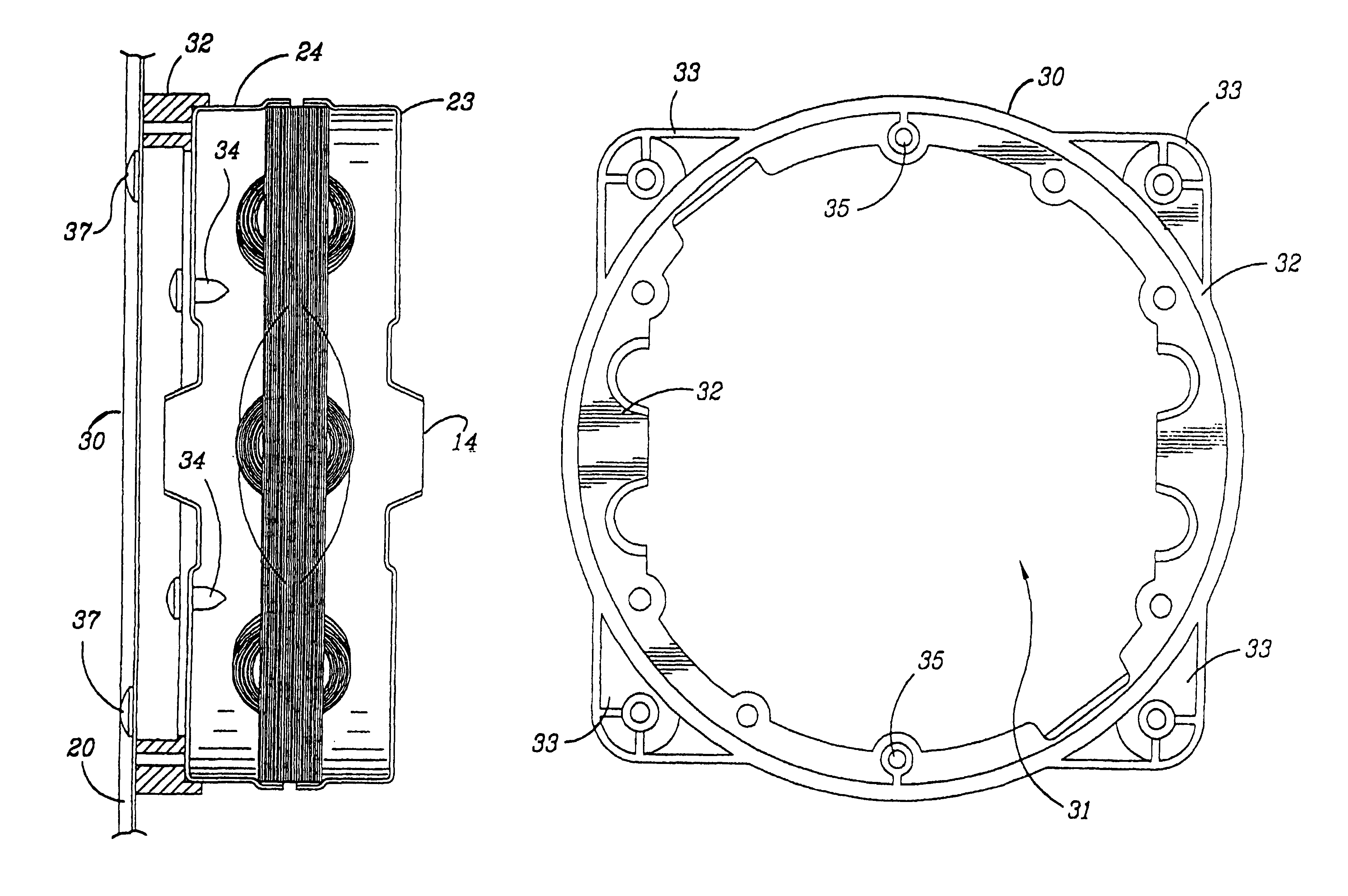
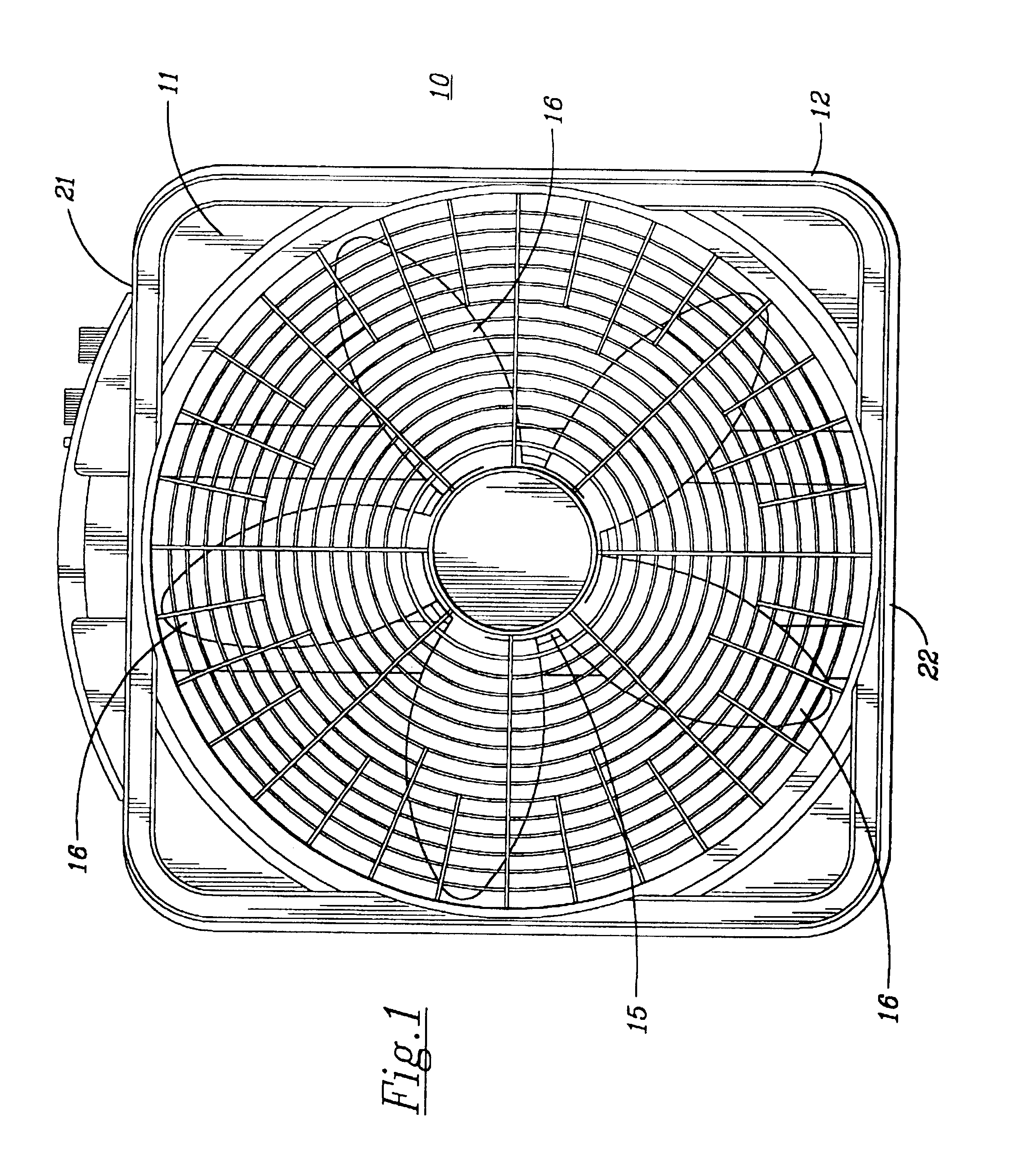
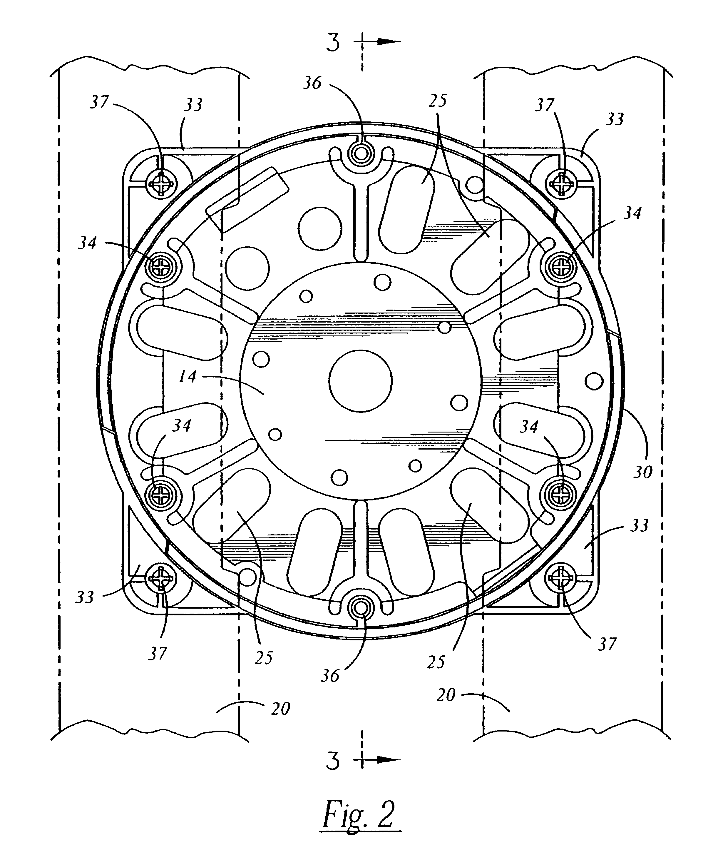
[0028]Referring now more particularly to FIGS. 1-4, inclusive, a box fan 10 is illustrated which has a front grill 11, an outer rectangular fan housing 12, a fan motor 14, with a fan hub 15, and a plurality of fan blades 16 extending therefrom.

[0029]The front grill 11 is preferably of molded synthetic plastic and the fan housing 12 is preferably of stamped metal.

[0030]A rear grill (not shown) would also be provided, which could having a design similar to front grill 11.

[0031]The fan housing 12 has a pair of spaced vertical brackets 20 extending from the top 21 of the housing 12 to the bottom 22, which brackets 20 are preferably of metal, to add strength and rigidity to the...


PUM


Abstract

An insulated box fan, which includes an outer metal housing with two vertical metal brackets to which a plastic isolator ring is attached, and which ring is also attached to the fan motor, to electrically insulate it from the fan housing, and to direct additional cooling air to the fan motor.

Description

BACKGROUND OF THE INVENTION[0001]1. Field of the Invention[0002]This invention relates to an insulated box fan of the type wherein the motor is electrically insulated from the rest of the fan by an isolator ring.[0003]2. Description of the Prior Art[0004]Box fans are perhaps the most common fan in the industry. Historically, box fans are constructed of metal and plastic and are one of the least expensive fans, they provide a high volume of air, are of relatively light weight, are sturdy and long lasting, are versatile in that they can be placed on virtually any flat surface, and are stable and resist toppling.[0005]With the use in fans of six pole motors and the increasing use of four pole motors, which use capacitors and consequent higher operating voltages, problems can arise if the fan is placed into a window, and the air being moved by the fan becomes moisture laden air, or if water comes directly onto the fan.[0006]One of the problems from moisture laden air is that the water m...

Claims


Application Information

Patent Timeline
IPC IPC(8): F04B17/00F04D25/06
CPCF04D25/06
Inventor LITVIN, CHARLES
Owner LASKO OPERATION HLDG LLC
Learn More