Coaxial cable compression connector

a compression connector and coaxial cable technology, applied in the direction of electrical equipment, connection, coupling device connection, etc., can solve the problems of not being able to prevent radiation leakage as effectively, and the technician is unable to use too much force to effect the interconnection

Active Publication Date: 2007-02-22
PPC BROADBAND INC
View PDF8 Cites 53 Cited by
  • Summary
  • Abstract
  • Description
  • Claims
  • Application Information

AI Technical Summary

Benefits of technology

[0006] Briefly stated, a compression connector for a coaxial cable includes a unitary plastic body with a post connected inside the plastic body and a nut connected to the post. An O-ring seals the connection between the nut and the plastic body. A compression ring is connected to an outside of the plastic body. A reinforcing shield is also connected to the outside of the plastic body. The reinforcing shield serves to reinforce the plastic body when the compression ring is moved to its compressed position, so that softer plastics can be used for the plastic body. The reinforcing shield and compression ring also protect the entire outside of the plastic body from the environment.
[0007] According to an embodiment of the invention, a compression connector for a coaxial cable includes a unitary plastic body; a post connected inside the plastic body; a nut connected to the post; a compression ring connected to an outside of the plastic body; and a reinforcing shield, separate from the nut, connected to an outside of the plastic body, and wherein the reinforcing shield and compression ring protect the entire outside of the plastic body from the environment when the compression ring is in both a compressed position and an uncompressed position.
[0009] According to an embodiment of the invention, a compression connector includes a unitary plastic body; means for connecting a post inside the plastic body; means for connecting a nut to the post; sealing means for sealing a connection between the nut and the plastic body; means for connecting a reinforcing shield to an outside of the plastic body, and means for connecting a compression ring to an outside of the plastic body; wherein the reinforcing shield and compression ring protect the entire outside of the plastic body from the environment when the compression ring is in both a compressed position and an uncompressed position.

Problems solved by technology

The principal difference between hard-line and drop cables, apart from the size of the cables, is that hard-line cables include a rigid or semi-rigid outer conductor, typically covered with a weather protective jacket, that effectively prevents radiation leakage and protects the inner conductor and dielectric, while drop connectors include a relatively flexible outer conductor, typically braided, that permits their bending around obstacles between the transition or junction box and the location of the device to which the signal is being carried, i.e., a television, computer, and the like, but that is not as effective at preventing radiation leakage.
A compression tool that slides the compression body into the connector is used by the technician to effect the connection, and due to the physical constraints of the compression member and connector body, it is impossible for the technician to use too much force to effect the interconnection.

Method used


Image

  • Coaxial cable compression connector
  • Coaxial cable compression connector
  • Coaxial cable compression connector

Examples


Embodiment Construction

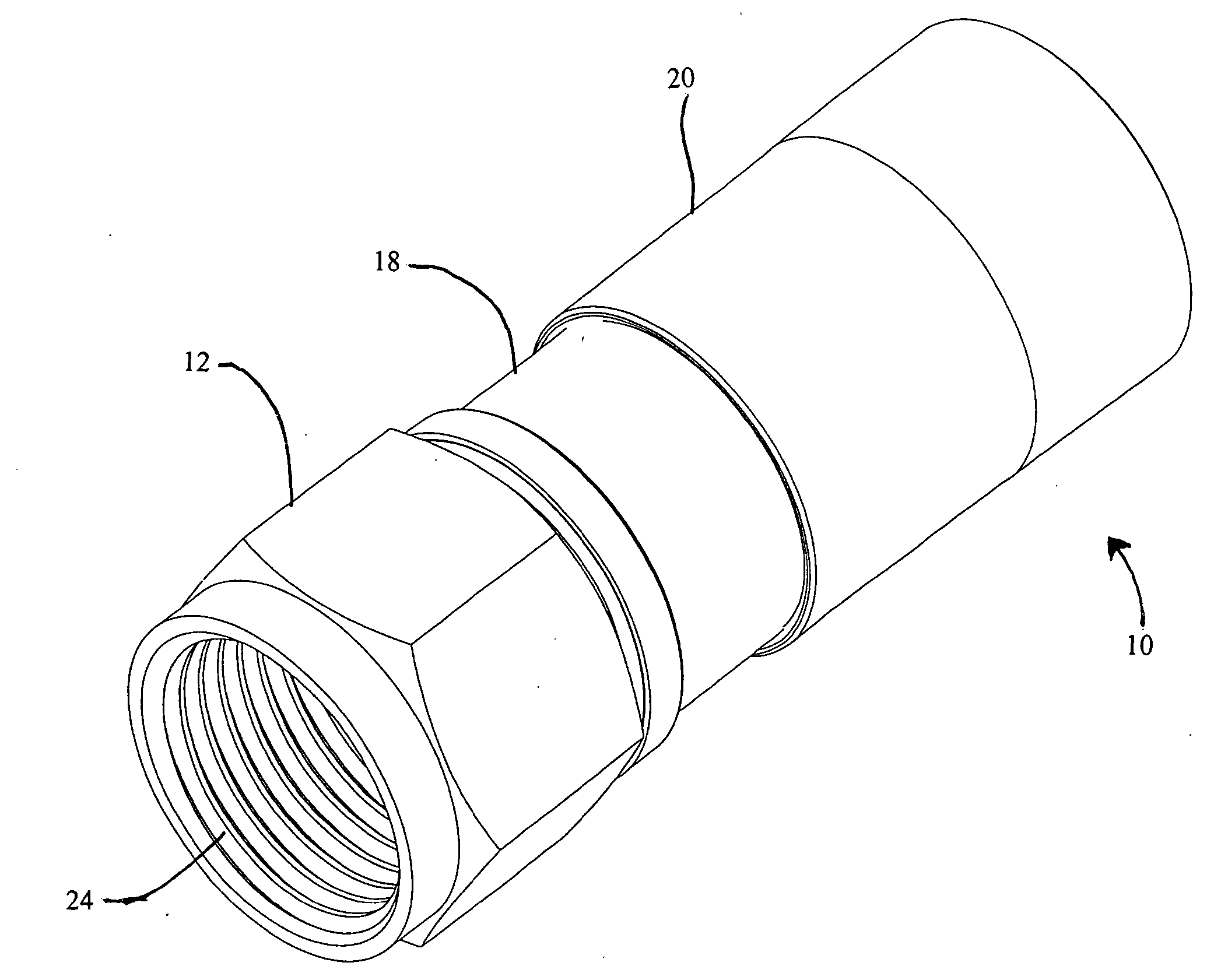
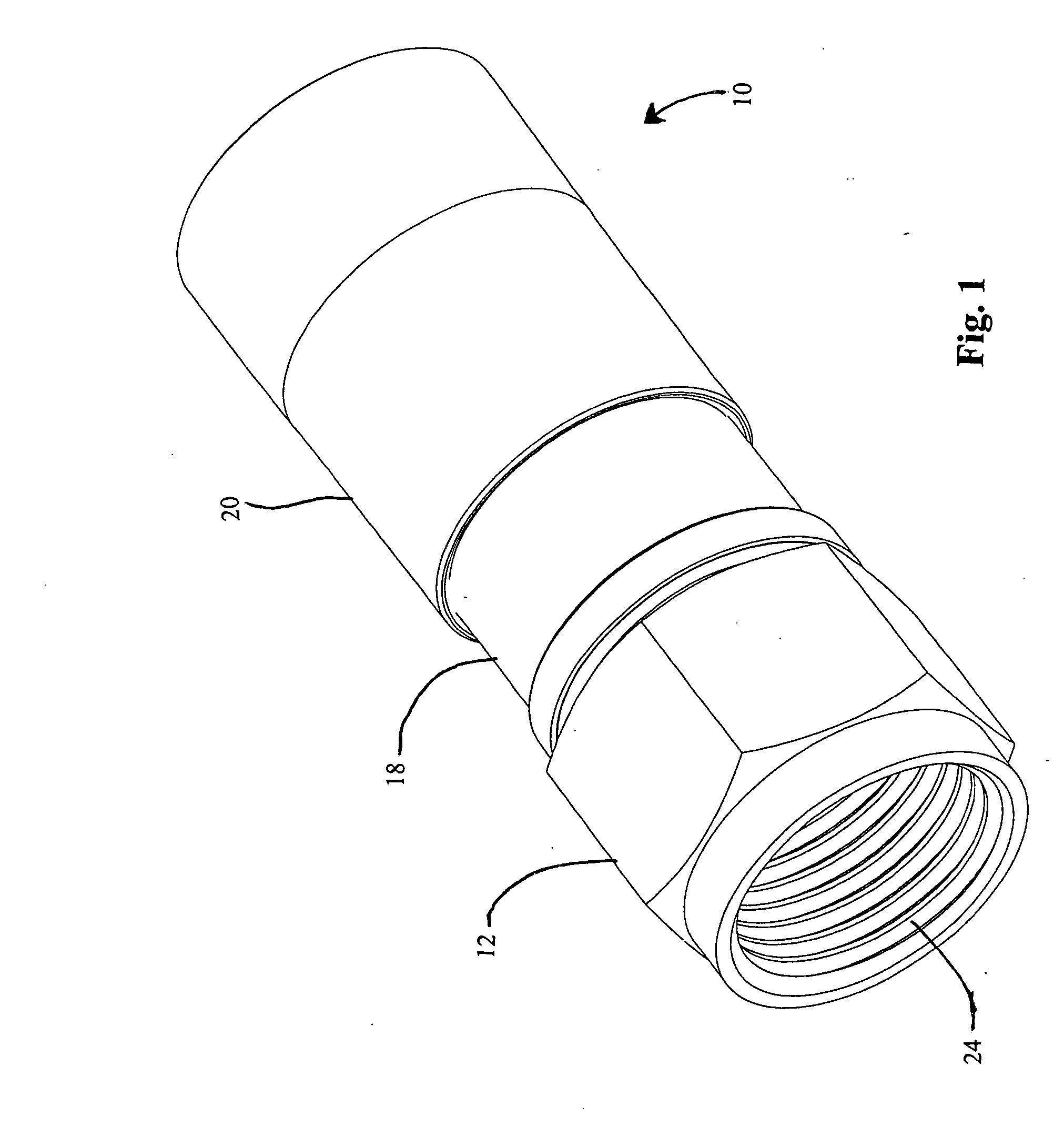
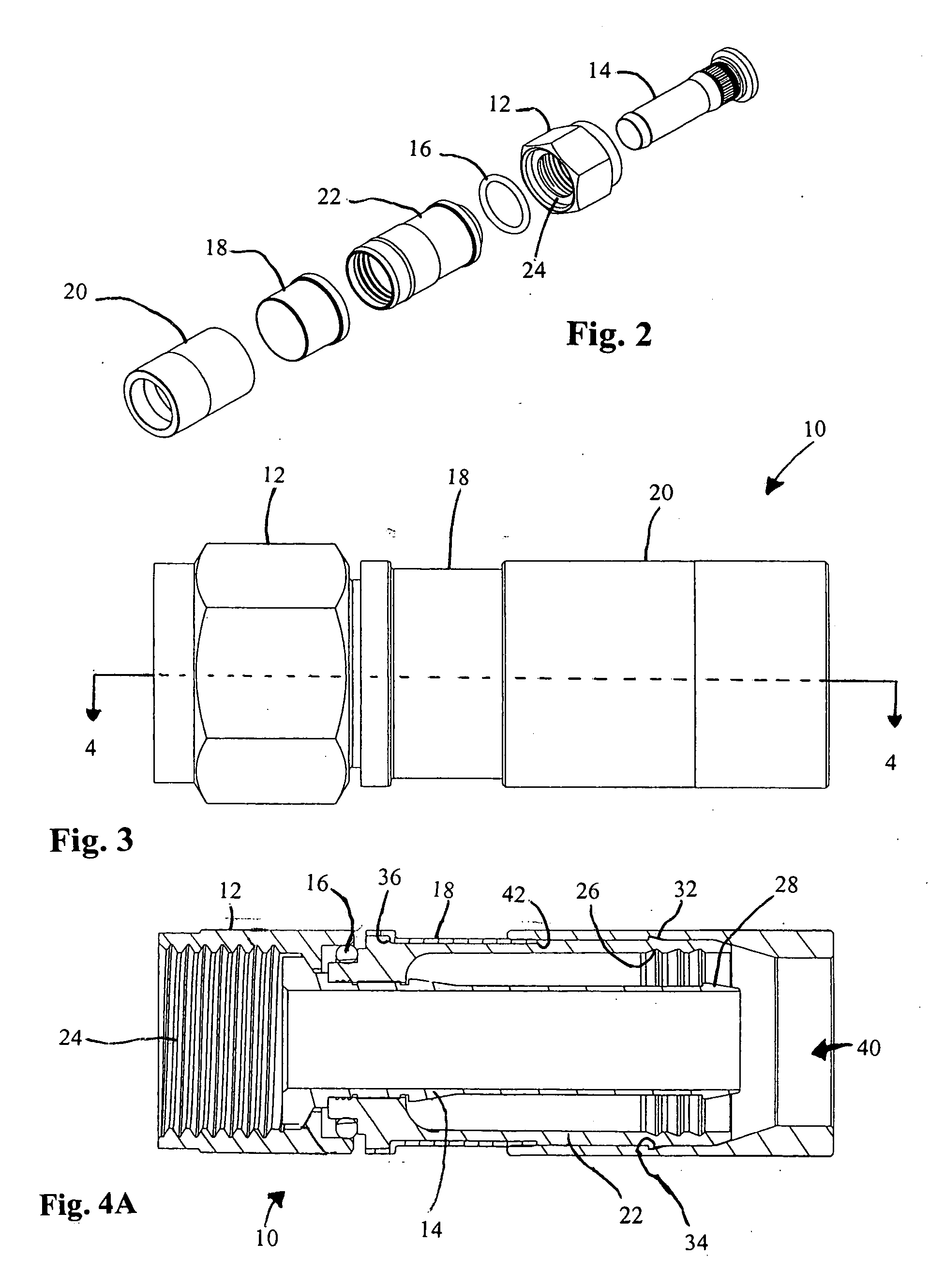
[0023] Referring to FIGS. 1-2, a coaxial cable compression connector 10 according to an embodiment of the invention is shown. A plastic body 22 is partly covered by a reinforcing shield 18 and partly covered by a compression ring 20. Compression ring 20 is preferably of metal but optionally is of plastic. A post 14 is disposed inside plastic body 22. A nut 12, preferably of metal for its conductive properties but optionally of plastic or composite material, is threaded with a thread 24 to permit connecting connector 10 to an equipment port or other device. An O-ring 16 preferably prevents moisture from entering connector 10 from the interface between nut 12, post 14, and plastic body 22.

[0024] Referring to FIGS. 3-8, additional details of connector 10 are shown. Shield 18 is held in place by shoulders 36 and 42 of plastic body 22. Plastic body 22 preferably includes a plurality of serrations 26, which, in conjunction with barbed tip 28 of post 14, provide a tight fit of the cable (...


PUM


Abstract

A compression connector for a coaxial cable includes a unitary plastic body with a post connected inside the plastic body and a nut connected to the post. An O-ring seals the connection between the nut and the plastic body. A compression ring is connected to an outside of the plastic body. A reinforcing shield is also connected to the outside of the plastic body. The reinforcing shield serves to reinforce the plastic body when the compression ring is moved to its compressed position, so that softer plastics can be used for the plastic body. The reinforcing shield and compression ring also protect the entire outside of the plastic body from the environment.

Description

CROSS-REFERENCE TO RELATED APPLICATIONS [0001] This application claims priority from and is a continuation in part of co-pending U.S. application Ser. No. 11 / 180,757 filed on Jul. 13, 2005 and entitled COAXIAL CABLE COMPRESSION CONNECTOR, incorporated by reference herein.FIELD OF THE INVENTION [0002] This invention relates generally to the field of coaxial cable connectors, and more particularly to a compression connector with a unitary plastic body having an exterior reinforcing shield. BACKGROUND OF THE INVENTION [0003] Coaxial cable is a typical transmission medium used in communications networks, such as a CATV network. The cables which make up the transmission portion of the network are typically of the “hard-line” type, while those used to distribute the signals into residences and businesses are typically “drop” connectors. The principal difference between hard-line and drop cables, apart from the size of the cables, is that hard-line cables include a rigid or semi-rigid oute...

Claims


Application Information

Patent Timeline
Patent Type & Authority Applications(United States)
IPC IPC(8): H01R9/05
CPCH01R9/0518H01R13/5202H01R13/5205H01R2103/00H01R13/6584H01R13/6593
Inventor MONTENA, NOAHAMIDON, JEREMY
Owner PPC BROADBAND INC
Why Eureka
Try Eureka