

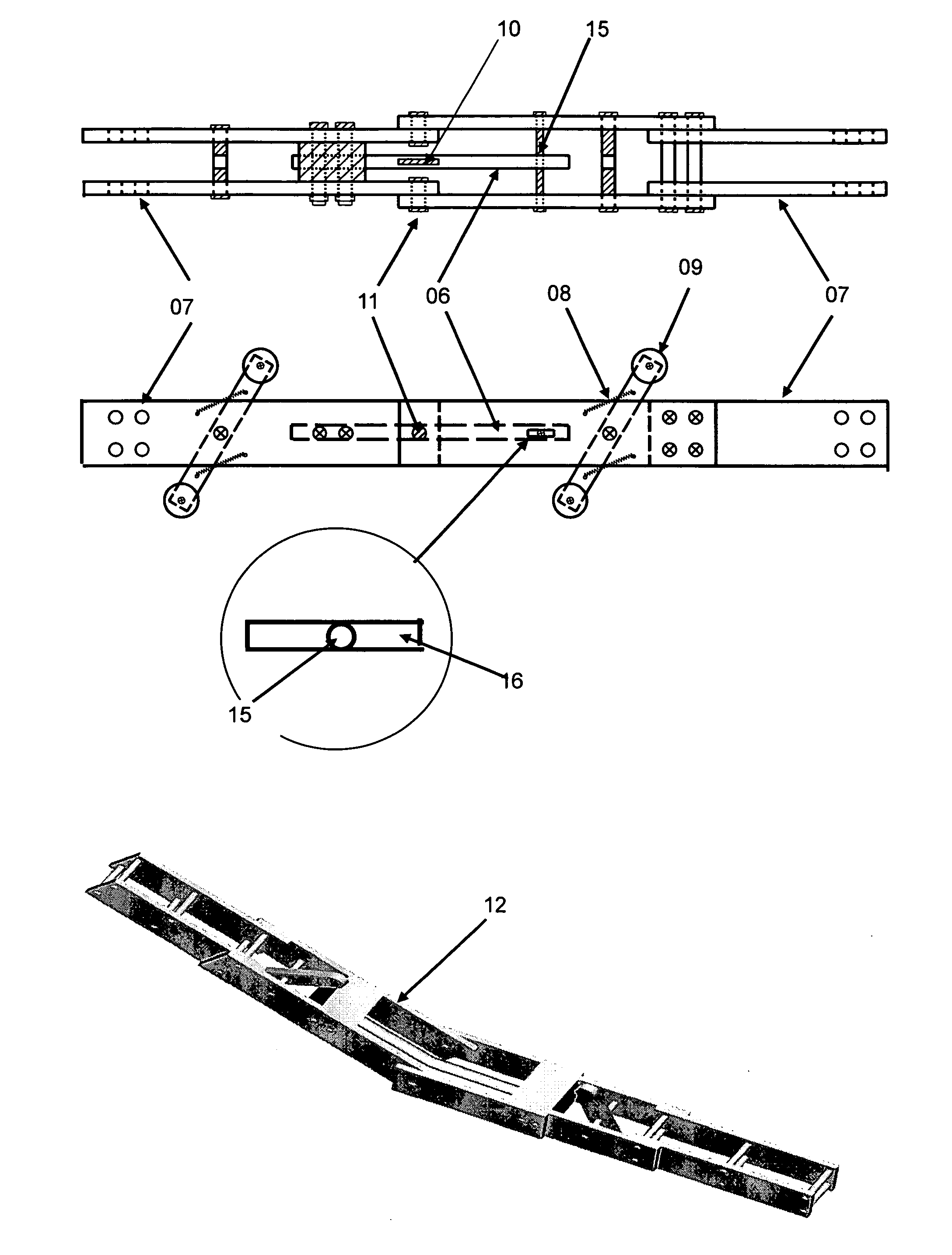
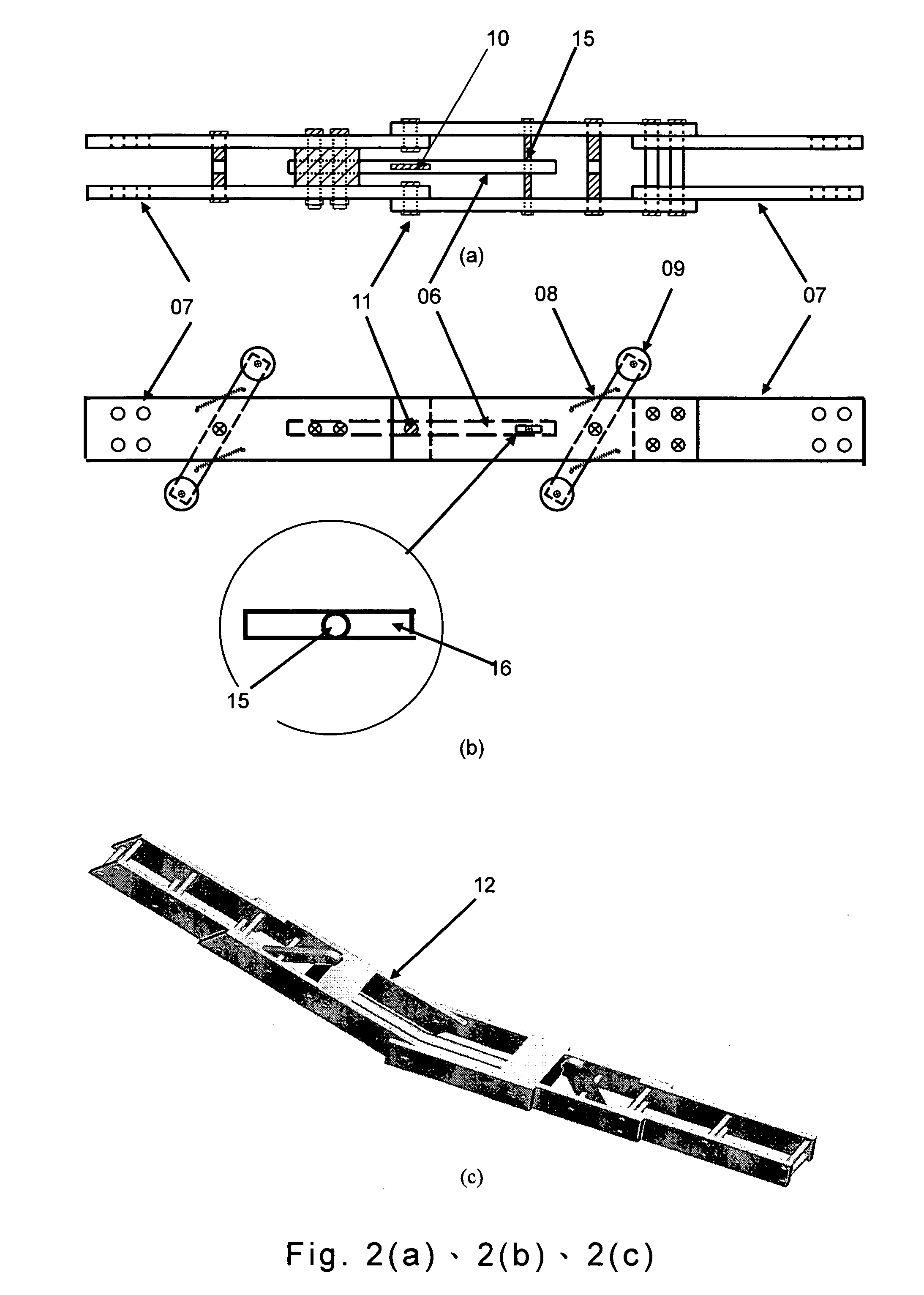
Fiber bragg grating sensored segmented deflectometer for ground displacement monitoring
a technology of segmented deflectometer and fiber bragg grating, which is applied in the direction of mechanical measuring arrangement, optical radiation measurement, instruments, etc., can solve the problems of time-consuming, electrical system prone to short circuit, and system impracticality, and achieve the effect of sensitivity and range adjustmen
- Summary
- Abstract
- Description
- Claims
- Application Information
AI Technical Summary
Benefits of technology
Problems solved by technology
Method used
Image

Examples
embodiment 1 (
A LABORATORY DEMONSTRATION)
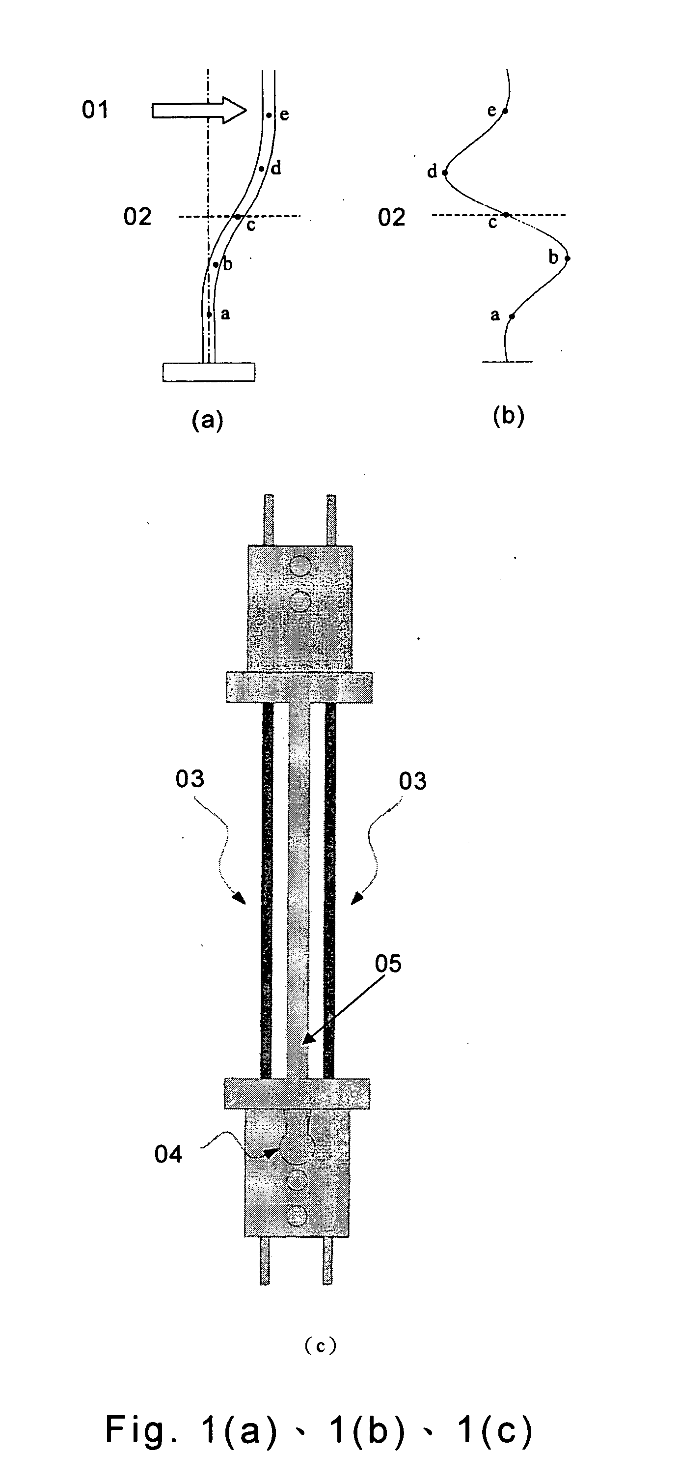
[0032] To demonstrate the effectiveness of the FBG-SD as a means to monitor ground movement, a series of experiments were conducted in the laboratory under controlled conditions. Two, 9-m long inclinometer casings were tied together with steel blocks to assure these casings have the same mount of lateral movements. The inclinometer casings were set up vertically against a stairway that was attached to a 3-m thick concrete reaction wall in a structural testing laboratory. A total of eight FBG-SD units were connected together to form a string and inserted into one of the inclinometer casings. An IP was lowered in the other casing to establish the IP initial readings. The two inclinometer casings were then forced to deform simultaneously by pushing the steel blocks against the stairway. Upon fixing the casings in their deformed position, the FBG-SD and IP readings were taken again. Once inserted, the FBG-SD's were left in place throughout the experiment; read...
embodiment 2 (
SAFETY MONITORING OF A RIVER DIKE)
[0034] The inventor has applied the newly invented FBG-SD as a means to monitor the integrity of a Yellow river dike. The test site was located at dike No.24 in Wu-Tze County, Honan Province, China. A string of FBG-SD with a total length of 8 m was inserted into an inclinometer casing 34 in FIG. 9. The inclinometer casing was installed at an angle of 45 degrees, 2 m from the edge and parallel to the surface of the river dike 33 in FIG. 9.
[0035] Soil erosion from the dike surface should result in an unloading condition and cause deformation to the FBG-SD sensor probe if the monitoring system performs properly. The sensor probe was embedded inside the dike body and thus not likely to be damaged by the dike surface erosion. The effectiveness of the design concept and sensitivity of the sensor system were verified by loading and subsequent unloading simulations on the dike surface. A 2-m wide wedge shaped pile of rock was formed along the face of the d...
embodiment 3 (
DEFORMATION MONITORING OF A DIAPHRAGM WALL DURING A DEEP EXCAVATION)
[0037] The FBG-SD system was to monitor the deformation of a 1.2-m thick, 15-m deep diaphragm wall during an internally braced deep excavation project in Beitou district of Taipei, Taiwan. The 8.1-deep excavation covered a square area of 100 m by 100 m, and was braced by two levels of cross lot struts. Two, 14-m deep inclinometer casings spaced at 1 m were tied to the reinforcement cage and then fixed inside of the diaphragm wall upon tremie concrete. A string of 11 FBG-SD's was inserted into one of the inclinometer casings leaving the other casing for IP measurements.
[0038]FIG. 14 shows the lateral movement induced by pre-loading of the second level struts when the excavation reached 5.8 m. The pre-loading pushed the diaphragm wall outwards by as much as 2 mm. As in the case of indoor experiments, the ground movements according to FBG-SD's were very similar to those of IP readings.
PUM
 Abstract
Description
Claims
Application Information