Connecting structure of water transfer pipeline

a technology of connecting structure and water transfer pipeline, which is applied in the direction of pipe joints, adjustable joints, mechanical devices, etc., can solve the problems of limited use and position of sprinklers b>5/b>, and achieve the effect of facilitating the use of water transfer pipes

Inactive Publication Date: 2007-03-01
HUNG DEN LU
View PDF4 Cites 8 Cited by
  • Summary
  • Abstract
  • Description
  • Claims
  • Application Information

AI Technical Summary

Benefits of technology

[0003] It is therefore a primary object of the present invention to provide a connecting structure of water transfer pipeline, including a connecting member, an outer collar and a ball seat. The connecting member is formed with a central flow way. An annular rib is formed on outer circumference of a middle section of the connecting member. One end of the connecting member is formed with a ball section, while the other end of the connecting member is an insertion end. The outer collar is fitted around the insertion end. An inner circumference of a middle section of the outer collar is formed with an annular groove in which a C-shaped retainer ring is inlaid. One face of the retainer ring abuts against the annular rib of the connecting member. A water pipe is fitted around the insertion end of the connecting member to clamp the C-shaped retainer ring, whereby the connecting member, the outer collar and the water pipe are connected with each other. The ball seat is formed with a central passage and has a tapered lower opening is fitted around the ball section of the connecting member. An upper opening of the ball seat is formed with an inner thread. An upper retainer collar is fitted around the other side of the ball section. A water transfer pipe with outer thread is screwed in the inner thread of the ball seat. The water transfer pipe compresses the upper retainer ring, whereby the ball section of the connecting seat is pivotally embraced by the ball seat. Accordingly, the water transfer pipe can be freely pivoted relative to the water pipe. This facilitates the use of the water transfer pipe.

Problems solved by technology

Therefore, the use and position of the sprinkler 5 are limited.

Method used


Image

  • Connecting structure of water transfer pipeline
  • Connecting structure of water transfer pipeline
  • Connecting structure of water transfer pipeline

Examples


Embodiment Construction

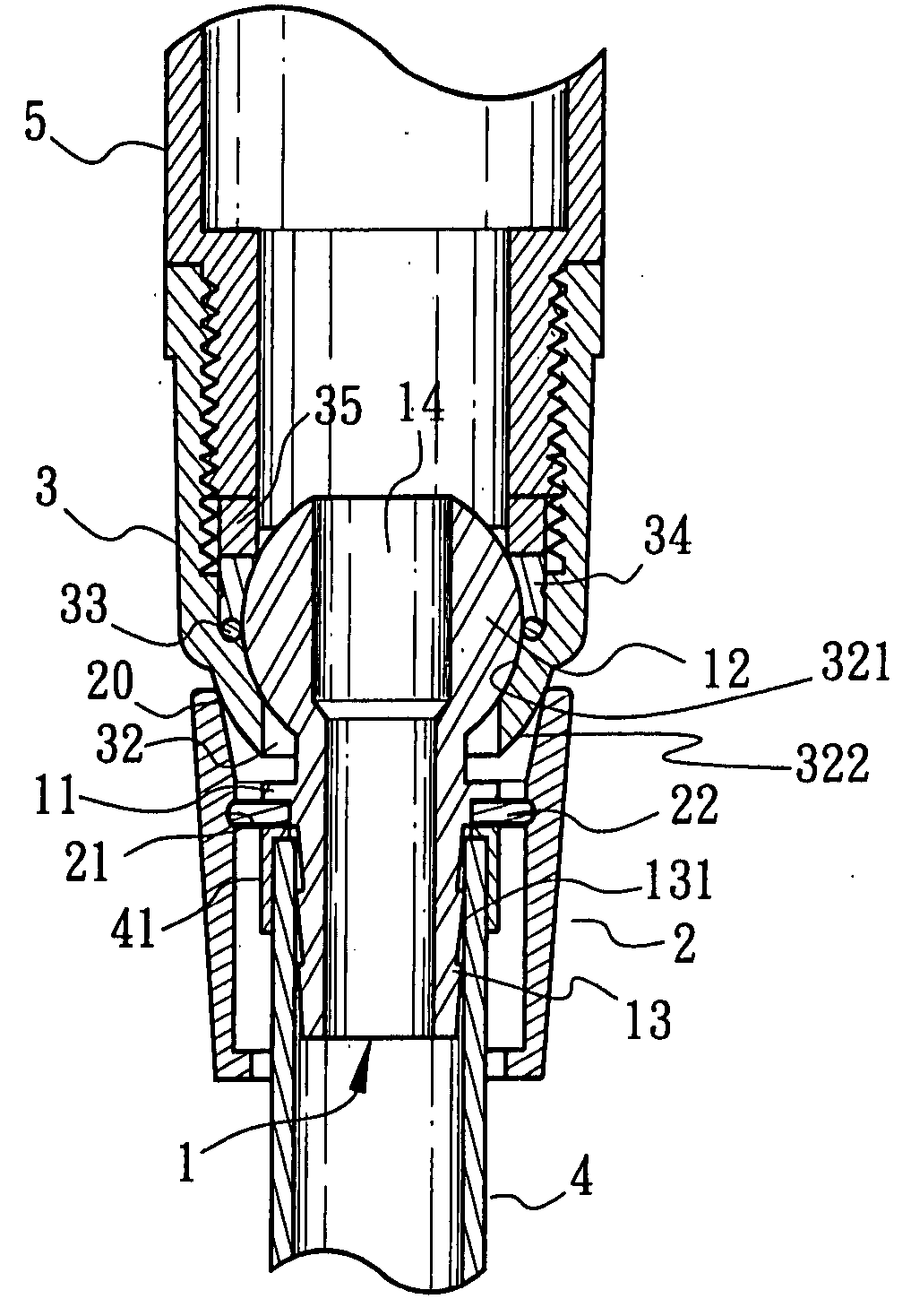
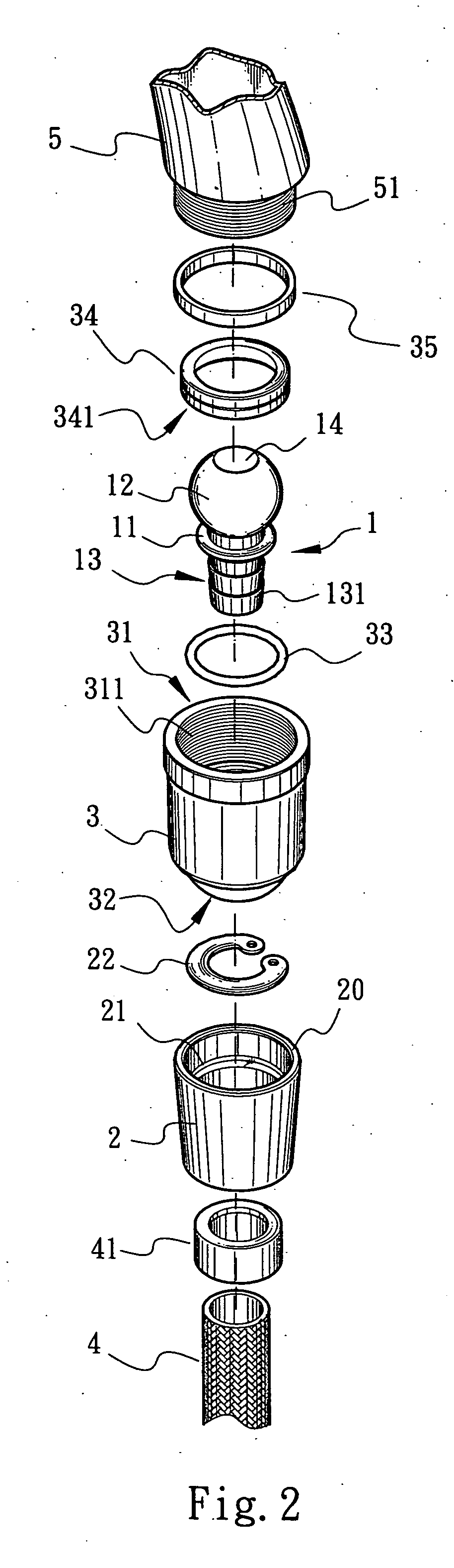
[0012] Please refer to FIGS. 1 to 3. The present invention includes a connecting member 1, an outer collar 2 and a ball seat 3. The connecting member 1 is formed with a central flow way 14. An annular rib 11 is formed on outer circumference of a middle section of the connecting member 1. One end of the connecting member 1 is formed with a ball section 12, while the other end of the connecting member 1 is an insertion end 13. The outer circumference of the insertion end 13 is formed with multiple tapered check flanges 131. The outer collar 2 is fitted around the insertion end 13. A front section of the outer collar 2 is formed with a contact opening 201. An inner circumference of a middle section of the outer collar 2 is formed with an annular groove 21 in which a C-shaped retainer ring 22 is inlaid. One face of the retainer ring 22 abuts against the annular rib 11 of the connecting member 1. A water pipe 4 with a lower retainer collar 41 is fitted in a rear end of the outer collar 2...


PUM


Abstract

A connecting structure of water transfer pipeline, including a connecting member having a central flow way, a ball section at one end and an insertion end at the other end. An outer collar is fitted around the insertion end. An inner circumference of the outer collar is formed with an annular groove in which a C-shaped retainer ring is inlaid. The retainer ring abuts against an annular rib of the connecting member. A water pipe is fitted around the insertion end of the connecting member to clamp the C-shaped retainer ring, whereby the connecting member, the outer collar and the water pipe are connected with each other. A ball seat formed with a central passage and having a tapered lower opening is fitted around the ball section of the connecting member. An upper opening of the ball seat is formed with an inner thread. An upper retainer collar is fitted around the other side of the ball section. A water transfer pipe with outer thread is screwed in the inner thread of the ball seat. The water transfer pipe compresses the upper retainer ring, whereby the ball section of the connecting seat is pivotally embraced by the ball seat.

Description

BACKGROUND OF THE INVENTION [0001] The present invention is related to a connecting structure of water transfer pipeline. By means of the connecting structure, a water transfer pipe can be freely pivoted relative to the water pipe. This facilitates the use of the water transfer pipe. [0002]FIG. 1 shows a connecting structure for connecting a water transfer pipe and a water pipeline such as a sprinkler and a water pipe. A retainer collar 401 is fitted around the outlet end of the water pipe 4. The retainer ring 401 is formed with an outer flange 402. A tubular connecting seat 6 is fitted around the retainer ring 401. The connecting seat 6 has an inner flange 61 at one end for abutting against the outer flange 402. The other end of the connecting seat 6 is formed with inner thread 62. An O-ring 63 is placed between the sprinkler 5 (or another water transfer pipe) and the retainer collar 401. Then the connecting seat 6 is screwed on the outer thread 51 of the sprinkler 5. The O-ring 63...

Claims


Application Information

Patent Timeline
Patent Type & Authority Applications(United States)
IPC IPC(8): F16L27/04
CPCF16L27/047F16L27/04
Inventor HUNG, DEN-LU
Owner HUNG DEN LU
Why Eureka
Try Eureka