
Precision syringe pump and manufacturing method thereof

a syringe pump, high-precision technology, applied in the field of medical devices, can solve the problems of poor reliability low precision, and high manufacturing cost, and achieve the effect of reducing the cost and improving the precision and reliability of the infusion speed of the syringe pump

Active Publication Date: 2017-03-02
MULTIDIMENSION TECH CO LTD
View PDF2 Cites 8 Cited by
  • Summary
  • Abstract
  • Description
  • Claims
  • Application Information

AI Technical Summary

Benefits of technology

The present invention relates to a syringe pump driven by a lead screw pump, which uses a magnetoresistive sensor and a Micro Control Unit (MCU) to feed back and control the infusion speed and monitor the position of the plunger in the syringe. This replacement of the step motor with a DC motor reduces the cost of the syringe pump. The use of the magnetoresistive sensor and low power consumption also reduces power consumption and facilitates the use of the syringe pump. The precision syringe pump of the present invention is characterized by high sensitivity, high reliability, low power consumption and low cost, and is convenient to use.

Problems solved by technology

A common practice is to use a step motor, and it is also feasible to use a linear or rotating potentiometer or an optical decoder to control the infusion speed, but these methods still have problems of low precision, poor reliability and high manufacturing cost.
At a low speed, the step motor is prone to low frequency vibration.
If the starting frequency is too high or the load is too large, it is easy to lead to a step loss or rotation blockage, and when the step motor stops, it is easy to lead to overshoot due to overhigh rotating speed.

Method used


Image

  • Precision syringe pump and manufacturing method thereof
  • Precision syringe pump and manufacturing method thereof
  • Precision syringe pump and manufacturing method thereof

Examples


Embodiment Construction

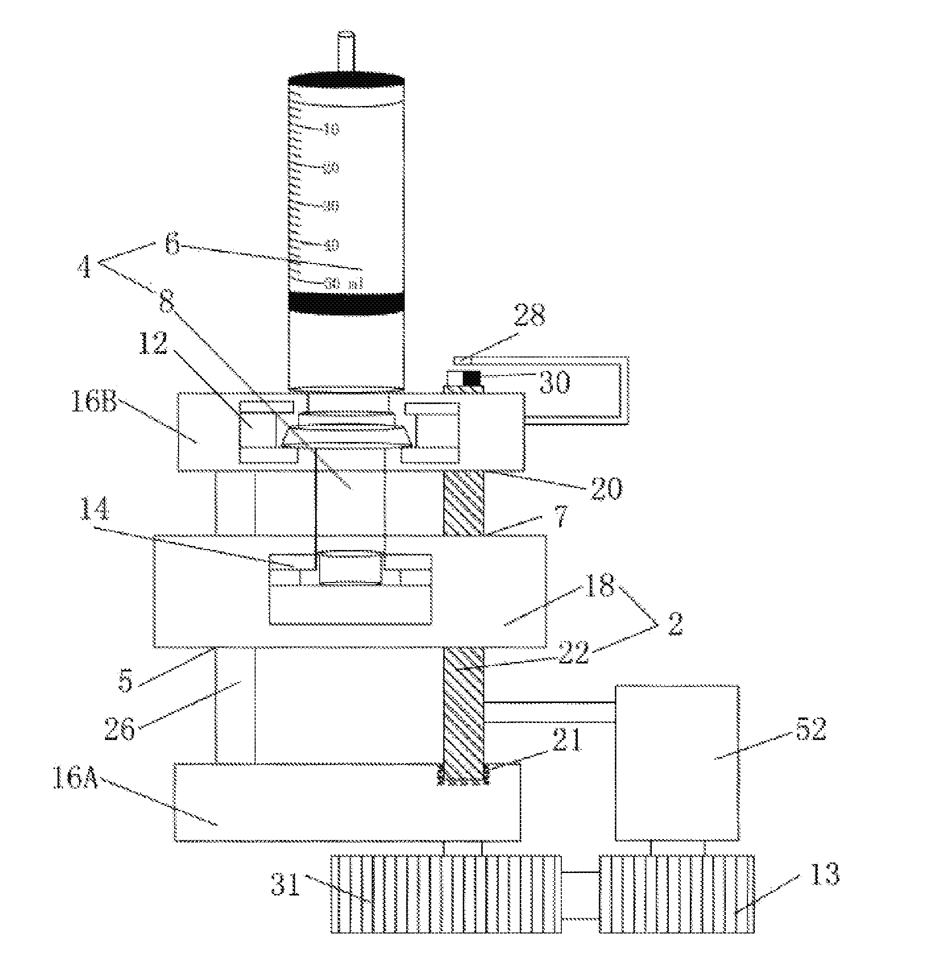
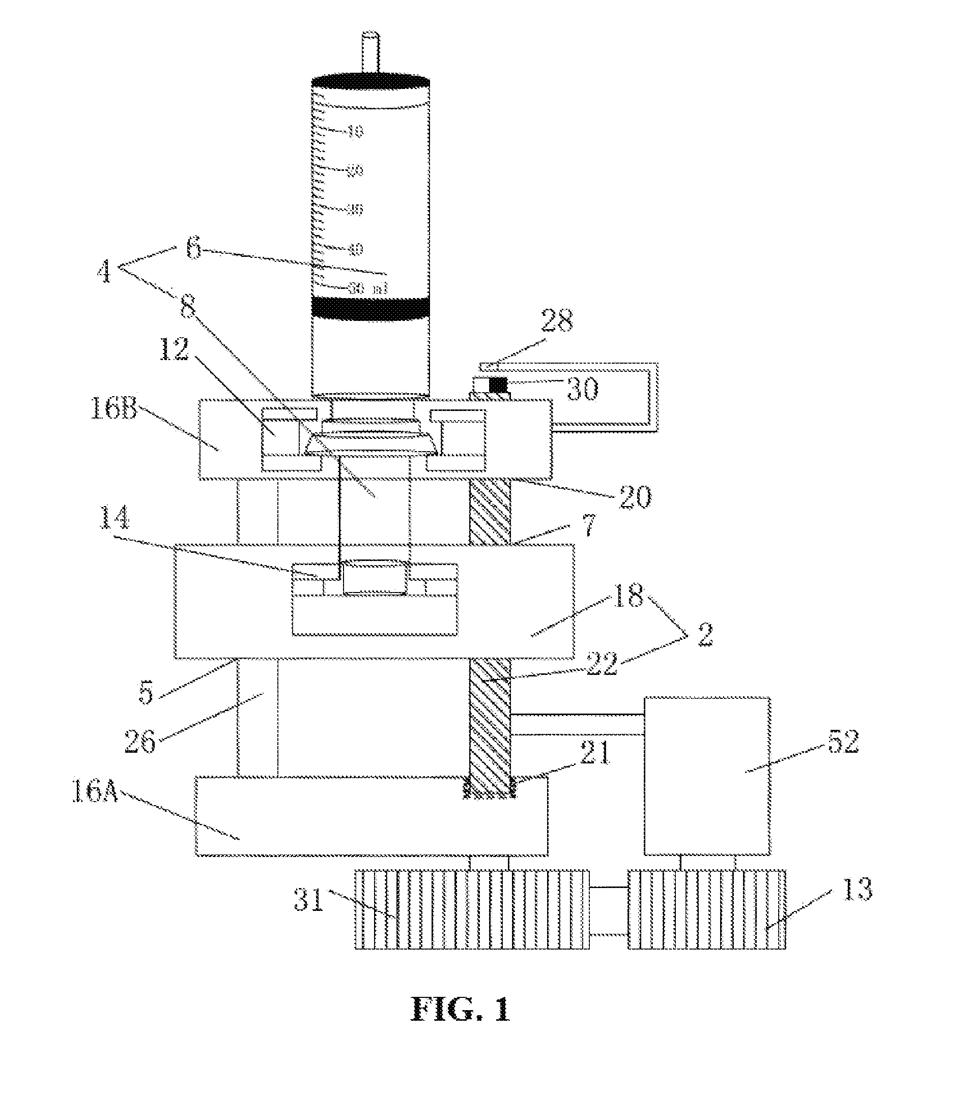
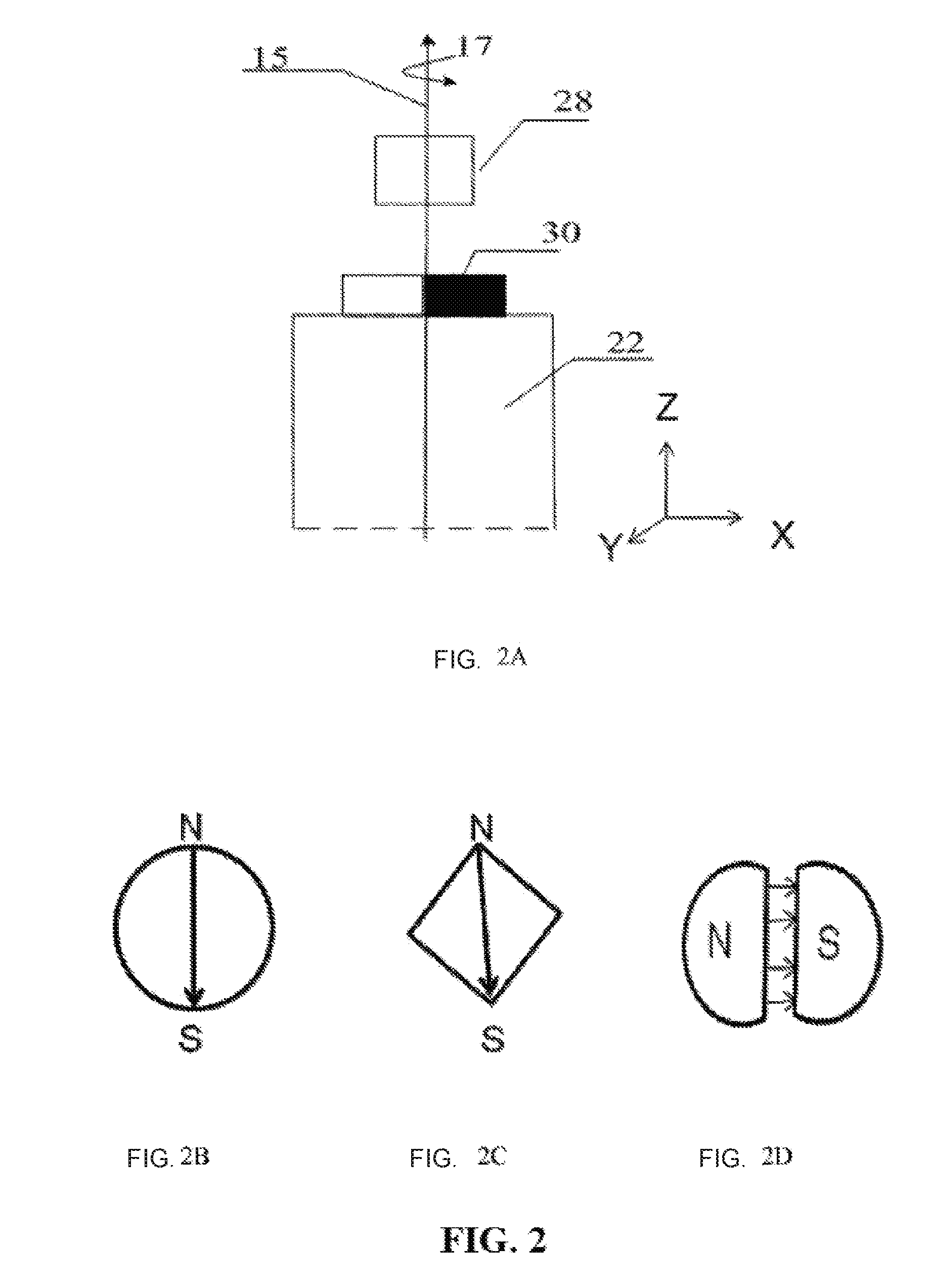
[0036]FIG. 1 is a top view of a syringe pump 2. A syringe pump 2 that can employ a syringe 4 comprises a motor 52, a lead screw 22 and a syringe driving head 18. The syringe 4 comprises a cylinder 6 and a plunger 8. The motor 52 drives the lead screw 22 to rotate clockwise or counterclockwise to drive the syringe driving head 18 and push the plunger 8 to move within the cylinder 6; the syringe pump 2 further comprises a magnetoresistive sensor 28, at least one permanent magnet 30 and an MCU 50; the permanent magnet 30 is located on the lead screw 22, and rotates therewith; the magnetoresistive sensor 28 can sense a magnetic field generated by the permanent magnet 30; an input end of the MCU 50 is connected with the magnetoresistive sensor 28, and an output end is connected with the motor 52; the MCU50 receives signals from the magnetoresistive sensor 28 and, according to the signal feedback, controls the direction and velocity of the lead screw 22 rotated by the motor 52.

[0037]One e...


PUM


Abstract

A precision syringe pump employing a syringe comprises a motor, a lead screw and a syringe driving head connected to the lead screw. The syringe comprises a cylinder and a plunger. The motor drives the lead screw to rotate clockwise or counterclockwise to drive the syringe driving head and push the plunger to move within the cylinder. The syringe pump further comprises: a magnetoresistive sensor, at least one permanent magnet and an MCU, the at least one permanent magnet being located on the lead screw and rotating therewith; the magnetoresistive sensor can sense the magnetic field generated by the at least one permanent magnet; the input end of the MCU is connected to the magnetoresistive sensor, and the output end of the MCU is connected to the motor; the MCU receives signals from the magnetoresistive sensor and controls, according to the signal feedback, the direction and velocity of the lead screw rotated by the motor. The precision syringe pump of the present invention is characterized by high sensitivity, high reliability, low power consumption and low cost, and is convenient to use.

Description

TECHNICAL FIELD[0001]The present invention relates to a medical device, and in particular, to a syringe pump for infusion.BACKGROUND ART[0002]In clinical use, infusion pumps allow automatically infusing liquid drugs or nutrients to patients intravenously at a set speed within a relatively longer time, which reduces the workload of medical staff and improves the security of infusion. According to different working principles, the infusion pumps are divided into different types, among which capacity pumps and syringe pumps are common. The capacity pumps can be driven by peristaltic pumps; and the syringe pumps can be driven by lead screw pumps. A motor drives a lead screw to rotate, changes rotational motion into linear motion, and pushes a plunger to inject liquid in a syringe into a patient's vein through a nut connected with the plunger. The precision of an infusion speed of the syringe pumps is higher than that of the capacity pumps, of which an error is about ±5%. However, in som...

Claims


Application Information

Patent Timeline
Patent Type & Authority Applications(United States)
IPC IPC(8): A61M5/142A61M5/168A61M5/172
CPCA61M5/14216A61M5/172A61M5/1684A61M5/16886A61M2207/00A61M2205/3317A61M2205/3365A61M2205/18A61M5/14236A61M5/1452A61M2205/3389
Inventor DEAK, JAMES GEZAJIN, YUQIN
Owner MULTIDIMENSION TECH CO LTD
Learn More