Method for fabricating Pt-MOx nanophase electrodes for highly efficient dye-sensitiized solar cell

Inactive Publication Date: 2005-01-27
GWANGJU INST OF SCI & TECH
View PDF0 Cites 9 Cited by
  • Summary
  • Abstract
  • Description
  • Claims
  • Application Information

AI Technical Summary

Benefits of technology

[0011] The metal oxide used for co-sputtering can have a high refractive index, e.g., a refractive index of 2 or more. Representative examples of the metal oxide as a target material include oxides of titanium, chromium, zinc, copper, etc., all of which have a refractive index of 2 or more. When these highly refractive metal oxides are co-sputtered together with platinum, they increase the reflectance of light and thus promote the excitation of dyes used, thereby improving the efficiency of a solar cell.
[0012] In addition, the metal oxide can include highly conductive oxides. Examples of such metal oxide typically include oxides of ruthenium, vanadium, tin, indium, etc., all of which have an electric conductivity of 0.1 S/m or more. When these highly conductive metal oxides are co-sputtered together with platinum, they help the

Problems solved by technology

However, the counter electrode thus fabricated has poor uniformity and poor adhesion to a substrate, causing an increase in dark current (see N. Papageorgiou, W. F. Maier and M. Gratzel, J. Electrochem. Soc. 144:876-883 (1997)).
However, the counter electrodes fabricated by electron-beam evaporation have disadvantages of high

Method used


Image

  • Method for fabricating Pt-MOx nanophase electrodes for highly efficient dye-sensitiized solar cell
  • Method for fabricating Pt-MOx nanophase electrodes for highly efficient dye-sensitiized solar cell
  • Method for fabricating Pt-MOx nanophase electrodes for highly efficient dye-sensitiized solar cell

Examples


Example

EXAMPLE 1

Fabrication of Platinum-Nickel Oxide (Pt—NiO) Counter Electrode

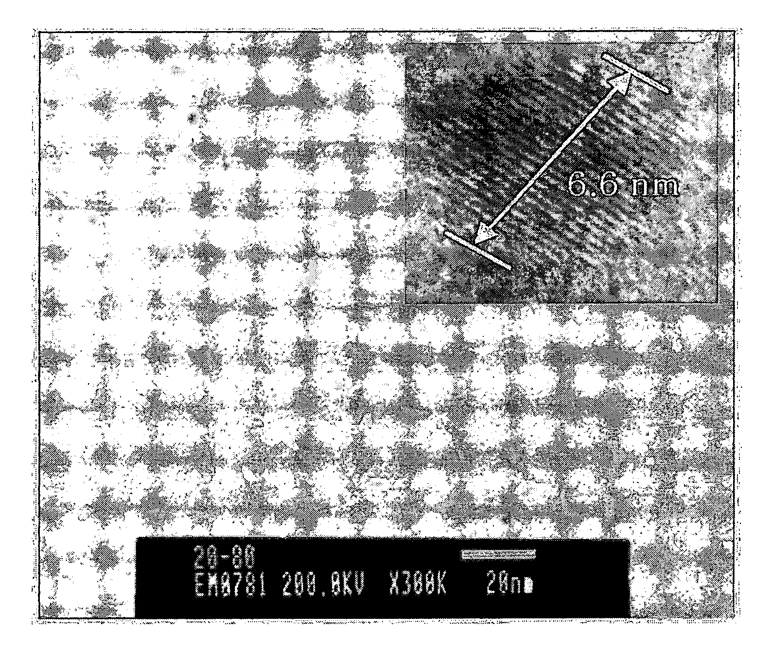
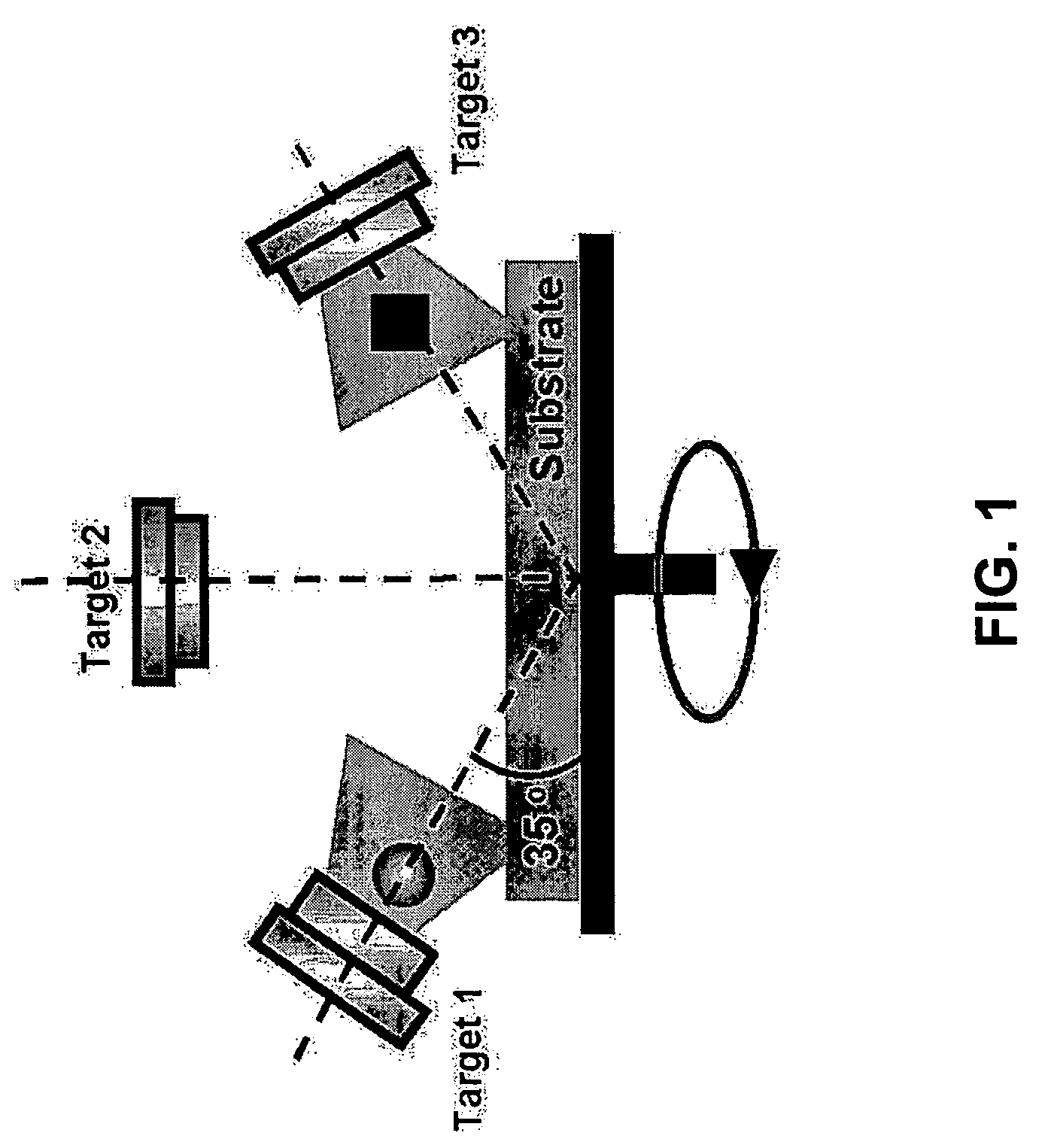
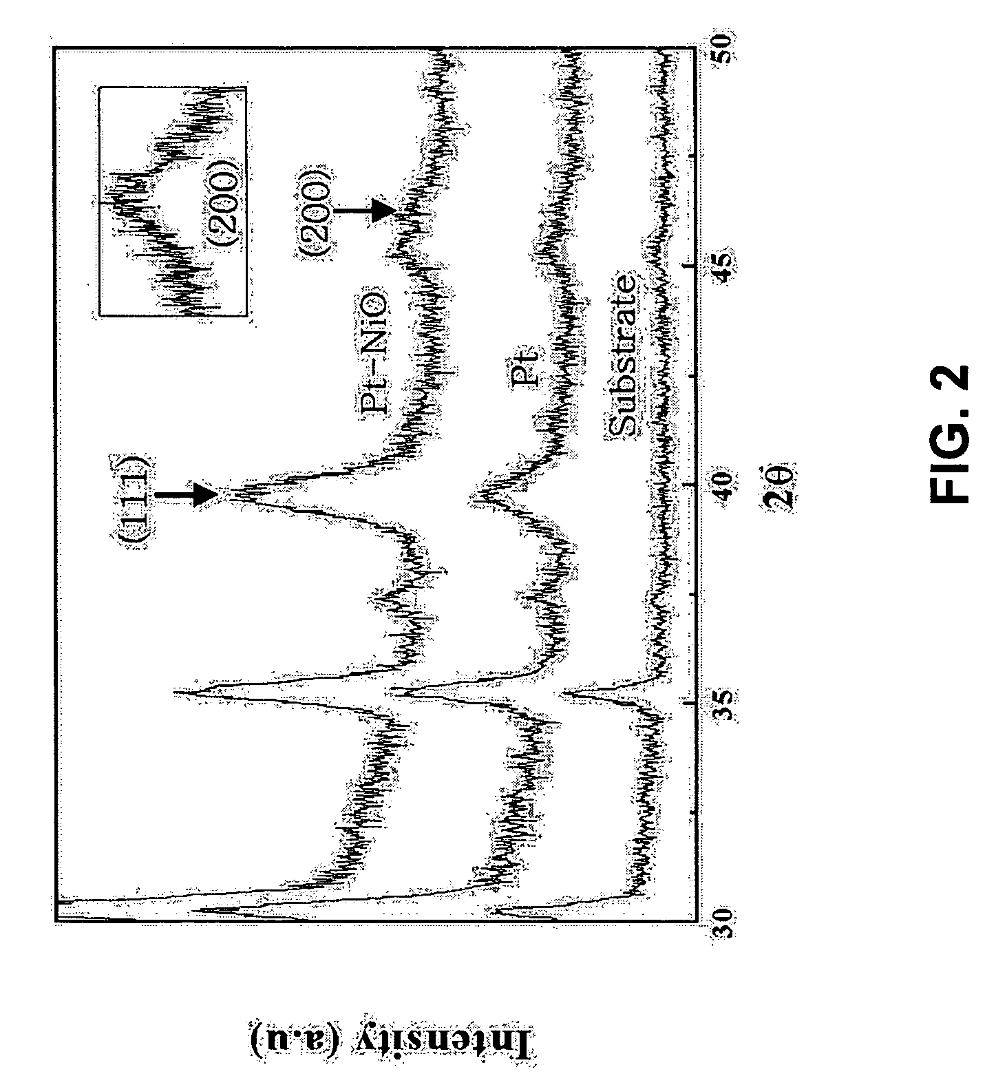
[0032] In this example, an electrode comprising nanocrystalline platinum and amorphous nickel oxide deposited on a surface of a substrate was fabricated using a co-sputtering system (RF magnetron sputtering system, Samwon Vacuum Co., Ltd., Korea) under Ar atmosphere. A glass plate coated with fluorine-doped tin oxide (SnO2) during evaporation was used as a substrate. Where a platinum target was arranged in the center of a chamber, and a nickel oxide target was arranged at one side of the chamber, RF powers of 30 W and 40 W were applied for 2 minutes to evaporate the two targets, respectively. In order to prepare a test piece for the transmission electron microscope (TEM) and transmission electron diffraction measurements of the electrode, a Cu grid was added to the substrate during evaporation. In addition, in order to compare the characteristics of the platinum-nickel oxide, a platinum electrode was fabricate...

Example

EXAMPLE 2

Fabrication of Platinum-Titanium (Pt—TiO2) Counter Electrode

[0036] In this example, an electrode comprising nanocrystalline platinum and amorphous titanium oxide deposited on the surface of a substrate was fabricated using the same system employed in as Example 1 under Ar atmosphere. Since the electrode was fabricated using the titanium oxide having a high refractive index, it exhibited a high reflectance. This improvement in reflectance causes the excitation of a dye and thus increases the efficiency of a solar cell to be manufactured. The principle is explained in FIG. 6.

[0037] A glass plate coated with fluorine-doped tin oxide (SnO2) during evaporation was used as a substrate. Where a platinum target was arranged in the center of a chamber, and a titanium oxide target was arranged at one side of the chamber, RF powers of 20 W and 80 W were applied for 2 minutes to evaporate the two targets, respectively. In order to prepare a test piece for the transmission electron m...


PUM


Abstract

A method for fabricating a counter electrode for a dye-sensitized solar cell includes co-sputtering platinum and a metal oxide as target materials to deposit nanocrystalline platinum and an amorphous metal oxide on the substrate. The counter electrode exhibits improved performances as an electro-catalyst to assist in the reduction of I3 during operation of a dye-sensitized solar cell.

Description

BACKGROUND OF THE INVENTION [0001] 1. Field of the Invention [0002] The present invention relates to a method for fabricating a counter electrode for a dye-sensitized solar cell, and more particularly to a method for fabricating a counter electrode for a dye-sensitized solar cell wherein the counter electrode comprises nanocrystalline platinum (Pt) and an amorphous metal oxide deposited on the substrate and serves as an electro-catalyst to assist in the reduction of I3− during operation of a dye-sensitized solar cell. The counter electrode exhibits improved electro-catalytic performances. [0003] 2. Related Art [0004] Dye-sensitized solar cells are novel devices of photo-electrochemical solar cells that can efficiently convert solar energy to electricity. The dye-sensitized solar cells are manufactured by chemically adsorbing a dye capable of forming electrons and holes when irradiated by light in the visible region, to a semiconductor material having a wide energy band gap. The dye-...

Claims


Application Information

Patent Timeline
IPC IPC(8): H01L31/04H01L31/00
CPCH01G9/2022Y02E10/542H01G9/2059H01G9/2031Y02P70/50H01L31/0224H01L31/04H01L31/18
Inventor KIM, SEOK-SOONPARK, KYUNG-WONYUM, JUN-HOSUNG, YUNG-EUN
Owner GWANGJU INST OF SCI & TECH
Why Eureka
Try Eureka