Block co-polymer photoresist

Active Publication Date: 2013-08-15
PT SPE SUBCO LLC
View PDF1 Cites 12 Cited by
  • Summary
  • Abstract
  • Description
  • Claims
  • Application Information

AI Technical Summary

Benefits of technology

[0039]In another preferred exemplary illustrative embodiment, the BCP may be used as a component in a multilayer stack. For example, the BCP may be sandwiched between an underlying hardmask and/or spin on carbon layers and conventional topcoat layers. The underlayers may provide increased etch resistance for pattern transfer to the substrate while the topcoat may provide anti-reflective properties or may be utilized as a protecting layer for the BCP, say during immersion lithography.
[0040]In another preferred exemplary illustrative embodiment, the BCP may be used in conjunction with a topcoat which is block copolymer. The block copolymer topcoat would be deposited onto the BCP layer after the self-assembly of the BCP. The self-assembly of the block copolymer topcoat may be directed by the pattern of the BCP layer. The block copolymer topcoat may be designed to have phase separated domains which have contrasting values for the index of refraction. This may allow for light to be “focused” by the topcoat domains with higher value for the index of refraction into selective underlying domains in the BCP layer. It may prove beneficial to have the effectively increased light doses due to this focusing in areas of the BCP which may contain the PAGs or the other photoactive compounds in the BCP layer.
[0041]In another preferred exemplary illustrative embodiment, the BCP may be used in conjunction with a topcoat which is block copolymer. The block copolymer topcoat would be deposited onto the BCP layer after the self-assembly of the BCP. The self-assembly of the block copolymer topcoat may be directed by the pattern of the BCP layer. The block copolymer topcoat may be designed to have phase separated domains which have contrasting absorptivity values at the wavelength or in the wavelength range used for exposure of the BCP. This may allow for further modification of the aerial image before it reaches the BCP since light of the same intensity that passes through topcoat domains with higher absorptivity will have lower intensity once they reach the BCP layer with respect to light that has passed through the topcoat domains with lower absorptivity. This may allow for the printing of patterns which are otherwise unobtainable or it may make the printing of

Problems solved by technology

During a post exposure bake (PEB), the resin then undergoes thermally induced reactions catalyzed by the photogenerated acid, resulting in a change in solubility for the resist.
For example, a high resolution resist which can produce features with low line-edge roughness, will, according to this relationship suffer from low sensitivity.
The different blocks, may have properties which make it energetically unfavorable for them to mix with each other at a molecular scale, thus resulting in the phase separation of the different blocks.
This usually results i

Method used


Image

  • Block co-polymer photoresist
  • Block co-polymer photoresist
  • Block co-polymer photoresist

Examples


Example

Materials

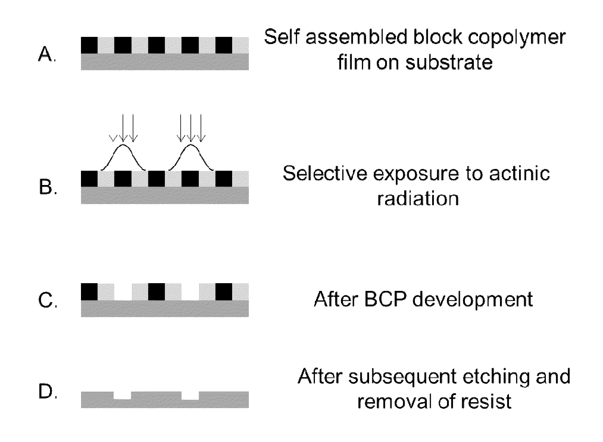
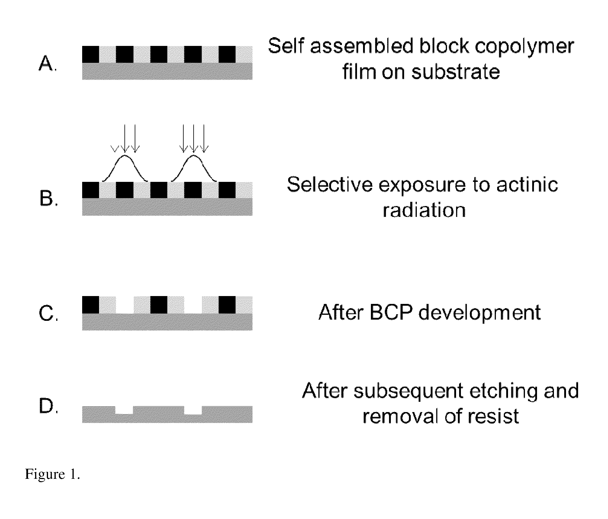
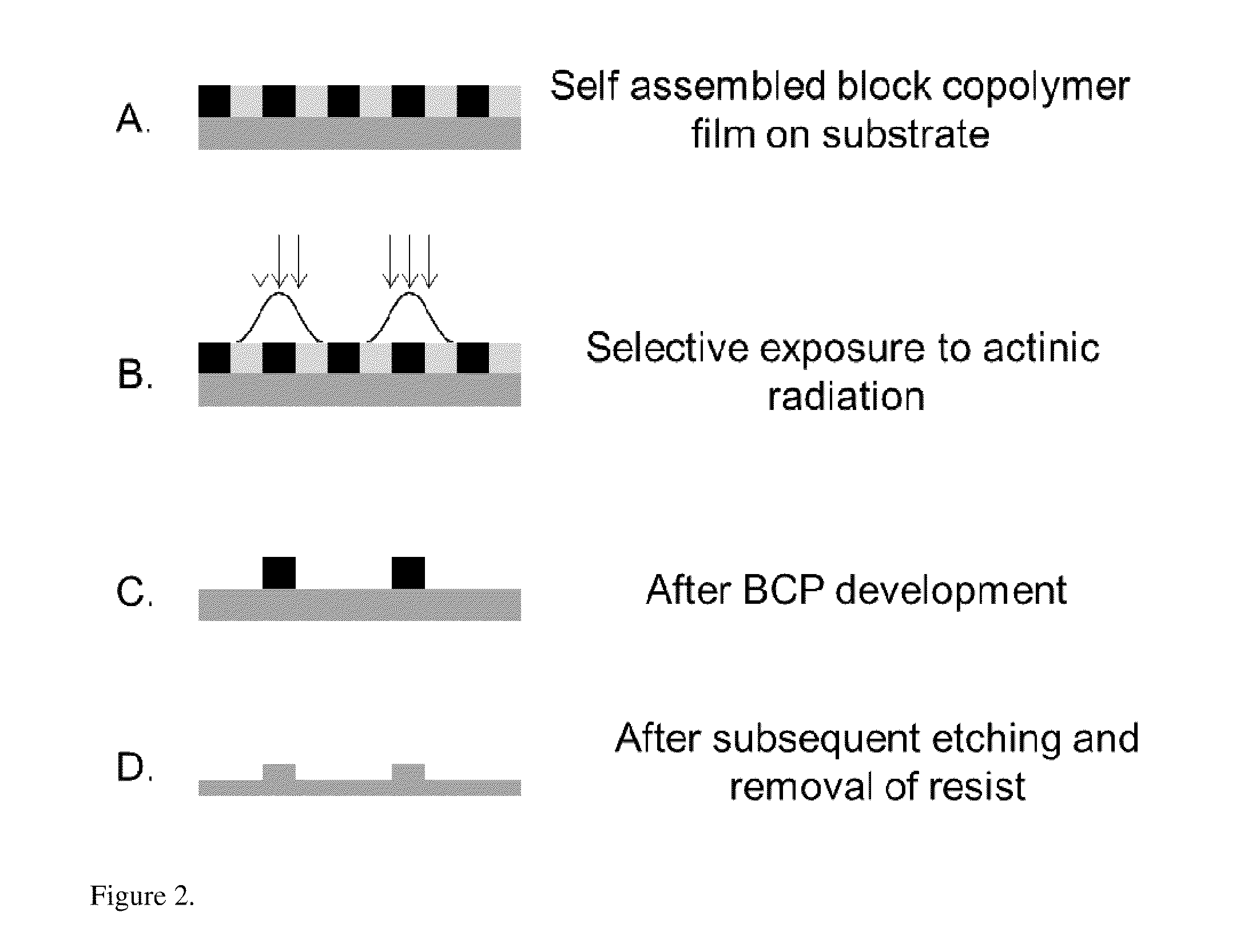
[0024]One preferred exemplary illustrative non-limiting embodiment provides for a block copolymer photoresist that is a cleavable block copolymer, which can undergo self-assembly to create a pattern of phase separated domains on a substrate. The self-assembly process may be directed by graphoepitaxy or chemical epitaxy. The linker group, at which the cleavage of the block copolymer will take place may be a variety of chemical units including, but not limited to: an ortho-nitrobenzyl group, an anthracene photodimer, triphenylmethyl (trityl) ether group, a tert-butyl carbamate group, a diphenyl methyl ether group, or any other groups that may be used to link two blocks of a block copolymer together and allow cleavage when exposed to various stimuli, including but not limited to: exposure to acid, base, or any other chemical agents as well as exposure to actinic radiation, etc. This linker group may be a molecule or may be a polymeric or oligomeric block itself, separating the...


PUM


Abstract

An integrated circuit is made by depositing a pinning layer on a substrate. A block copolymer photoresist is formed on the pinning layer. The block copolymer has two blocks A and B that do not self-assemble under at least some annealing conditions. The exposed block copolymer photoresist is processed to cleave at least some block copolymer bonds in the exposed selected regions. The exposed pinning layer is processed to create a chemical epitaxial pattern to direct the local self assembly of the block copolymer.

Description

CROSS-REFERENCE TO RELATED APPLICATIONS[0001]This non-provisional application claims the benefit of priority from U.S. Provisional Application Nos. 61 / 597,526 and 61 / 597,544 filed 10 Feb. 2012. This Application is related to co-pending commonly-assigned U.S. patent application Ser. No. 11 / 774,171 filed 6 Jul. 2001, which application claims the benefit of priority from Provisional Application No. 60 / 806,877 filed 10 Jul. 2006, and Provisional Application No. 60 / 870,795 filed 19 Dec. 2006; application Ser. No. 13 / 189,143 filed 22 Jul. 2011, which application is a divisional application of U.S. patent application Ser. No. 12 / 415,013 filed 31 Mar. 2009; which is a divisional application of U.S. patent application Ser. No. 10 / 792,377 filed 4 Mar. 2004, now U.S. Pat. No. 7,524,616 issued 28 Apr. 2009; which application claims the benefit of priority from Provisional Application No. 60 / 451,240 filed 4 Mar. 2003. The entire contents of each of these prior disclosures is incorporated herein ...

Claims


Application Information

Patent Timeline
IPC IPC(8): G03F7/004H01L29/06G03F7/20
CPCG03F7/004G03F7/20H01L29/06G03F7/0002B82Y40/00H01L21/0271B81C1/00031B81C2201/0149B82Y10/00G03F7/039G03F7/38H01L21/0274H01L21/324H01L21/82H01L27/04
Inventor COOPER, GREGORY D.WEHRENBERG, BRIAN L.
Owner PT SPE SUBCO LLC
Why Eureka
Try Eureka