Illumination system having a light mixer for the homogenization of radiation distributions

Inactive Publication Date: 2005-12-22
CARL ZEISS SMT GMBH
View PDF6 Cites 3 Cited by
  • Summary
  • Abstract
  • Description
  • Claims
  • Application Information

AI Technical Summary

Benefits of technology

[0031] The inventive arrangement of a plurality of beam splitters, which may for example comprise a transparent support with a beam-splitter layer applied on top, can ensure that each individual light ray passes through at least two beam splitters. In this way, each incident light ray is split more than twice so that, with suitably selected dimensions, both the temporal and spatial coherence levels can be reduced considerably. Furthermore, all the beam splitters of the first row on

Problems solved by technology

Fluctuations in these quantities generally lead to undesirable structure width fluctuations of the components to be produced.
Material and fabrication errors of these optical elements may in this case produce inhomogeneities of the intensity distribution.
Such glass rods do not, however, preserve the polarization state of the light passing through.
The beam splitters used in this case furthermore constitute additional virtual, spatially separated light sources so that the spatial coherence of the projection light is a

Method used


Image

  • Illumination system having a light mixer for the homogenization of radiation distributions
  • Illumination system having a light mixer for the homogenization of radiation distributions
  • Illumination system having a light mixer for the homogenization of radiation distributions

Examples


Example

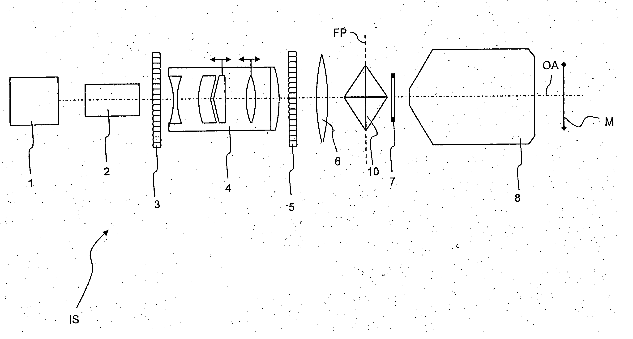
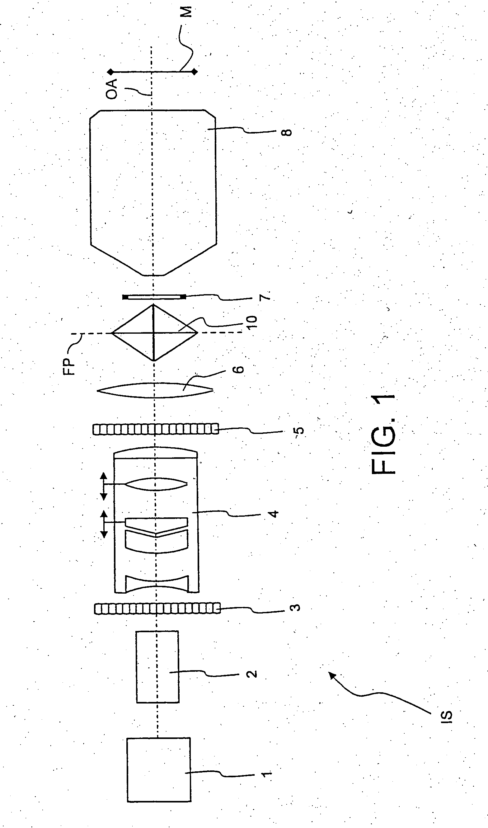
[0050]FIG. 1 shows an illumination system, denoted in its entirety by IS, of a microlithographic projection exposure apparatus in a highly simplified meridian section which is not true to scale. The illumination system IS comprises a laser 1 used as a light source, which produces a collimated light beam, a beam shaping device 2, a first optical raster element 3 which is the first element that increases the divergence of the light beam, a zoom-axicon objective 4 for setting different types of illumination, and a second optical raster element 5. Arranged in the beam path behind these, there are a condenser lens 6, a light mixer 10 through which a field plane FP passes, and an adjustable masking device 7 which can set the geometry of the light field passing through the reticle.

[0051] The illumination system IS furthermore comprises a masking objective 8, the masking device 7 being arranged in its object plane and a mask M being arranged in its image plane. The masking device 7 is thus...


PUM


Abstract

An illumination system of a microlithographic projection exposure apparatus contains a light mixer for the homogenization of radiation distributions. The latter may, in one embodiment, comprise at least one plane beam-splitter layer which is arranged between two transparent sub-elements, parallel to an optical axis of the illumination system. An alternative embodiment of a light mixer contains at least one row of beam splitters, wherein the beam splitters in at least one row are arranged mutually parallel, at an inclination angle with respect to an entry-side optical axis of the illumination system, and offset behind one another in a direction perpendicular to the entry-side optical axis.

Description

CROSS-REFERENCE TO RELATED APPLICATIONS [0001] This application claims priority of provisional U.S. patent application Ser. No. 60 / 578,521 filed Jun. 10, 2004. The full disclosure of this earlier application is incorporated herein by reference.BACKGROUND OF THE INVENTION [0002] 1. Field of the Invention [0003] The invention relates to an illumination system of a microlithographic projection exposure apparatus, having a light mixer for the homogenization of radiation distributions. [0004] 2. Description of the Related Art [0005] For the production of microstructured components, a plurality of structured layers are applied on a suitable substrate which, for example, may be a silicon wafer. In order to structure the layers, they are first covered with a photoresist which is sensitive to light of a particular wavelength range, for example light in the deep ultraviolet (DUV) spectral range. The wafer coated in this way is subsequently exposed in a projection exposure apparatus. A pattern...

Claims


Application Information

Patent Timeline
IPC IPC(8): G01B11/00G02B27/28G03F7/20
CPCG02B27/283G03F7/70583G03F7/70075
Inventor FIOLKA, DAMIANSINGER, WOLFGANGWANGLER, JOHANNES
Owner CARL ZEISS SMT GMBH
Why Eureka
Try Eureka