Method and device for lighting for dentists and other professionals

Inactive Publication Date: 2008-10-02
KATS VLADIMIR +2
View PDF3 Cites 0 Cited by
  • Summary
  • Abstract
  • Description
  • Claims
  • Application Information

AI Technical Summary

Benefits of technology

[0006]This arrangement would have the effect of giving increased lighting on the gener

Problems solved by technology

All these examples are cases where the professional needs to see the area of his work which is usually in a constricted place where v

Method used


Image

  • Method and device for lighting for dentists and other professionals
  • Method and device for lighting for dentists and other professionals

Examples


Example

[0012]As will be appreciated the present invention is capable of other and different embodiments than those discussed above and described in more detail below, and its several details are capable of modifications in various aspects, all without departing from the spirit of the invention. Accordingly, the drawings and description of the embodiments set forth below are to be regarded as illustrative in nature and not restrictive.

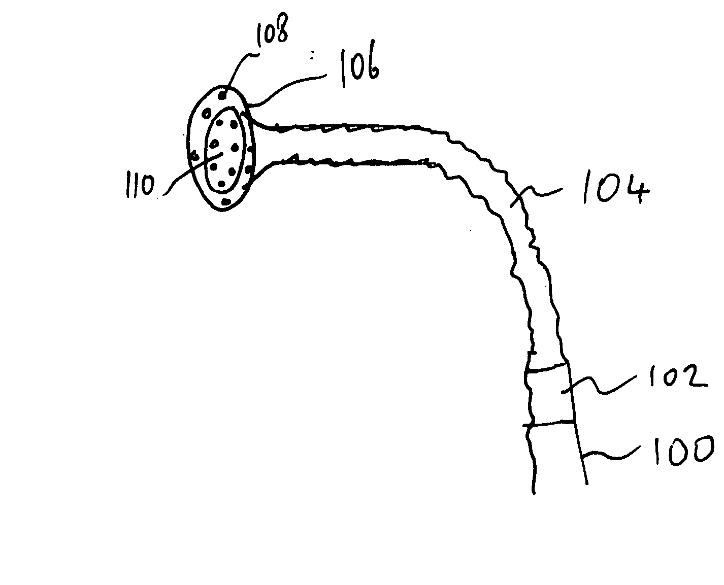
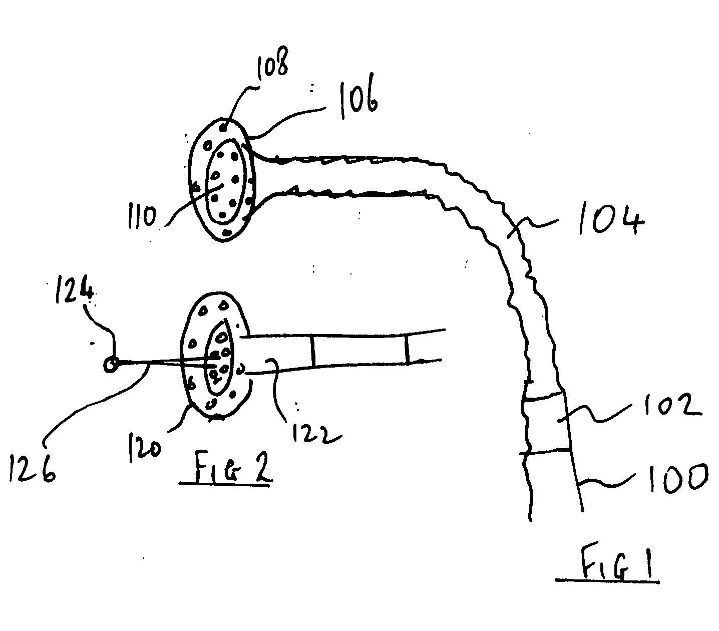
[0013]FIG. 1 shows the upper end of the light fitting 100 of this invention. A portion of this fitting is telescopic 102 being adjustable manually or electronically. Another portion of the fitting is made of flexible material 104 to aid the user to find the best angle for the light.

[0014]The head 106 of the light fitting 100 could be various shapes or sizes with many bulbs for example led lights 108 with a curved reflector 110 behind the bulbs.

[0015]The center portion of the head 106 could be extractable and retractable as described in more detail in FIG. 2.

[0...


PUM


Abstract

A light fitting with attachment to apparatus near a work area. Flexible and extendable connections to the bulbs of the light. Strong lighting bulbs attached to flexible and soft housings. Extendable and retractable portions of the said fitting to bring focused light as close as possible to the work area. Option of sensors to avoid collision with moving bodies.

Description

FIELD OF THE INVENTION[0001]This invention is in the field of lighting fixtures and in particular as they apply to dentists and other professionals and work environments.BACKGROUND OF THE INVENTION[0002]This invention comes to solve the difficulty professionals and dentists in particular experience when they need the best quality lighting to see the area on which they are working. Surgeons have a similar need for such lighting and many other areas of work for example, a car mechanic who is working under a vehicle. All these examples are cases where the professional needs to see the area of his work which is usually in a constricted place where visibility is often poor or partially obstructed and the professional's own body often obstructs the light from reaching the work area. This invention reveals a method of lighting that to a significant extent solves these lighting problems.SUMMARY OF THE INVENTION[0003]It is to be understood that both the foregoing general description and the ...

Claims


Application Information

Patent Timeline
IPC IPC(8): F21V21/32F21V21/28F21V21/088
CPCF21V7/0075F21V21/22F21V21/32F21V21/403F21W2131/202F21Y2101/02F21Y2115/10
Inventor KATS, VLADIMIRNITZAN, HIRSCHTIOMKIN, ALEXANDER
Owner KATS VLADIMIR
Why Eureka
Try Eureka