Input buffer design using common-mode feedback (CMFB)

Active Publication Date: 2007-03-01
MICRON TECH INC
View PDF9 Cites 12 Cited by
  • Summary
  • Abstract
  • Description
  • Claims
  • Application Information

AI Technical Summary

Benefits of technology

[0010] One exemplary embodiment provides an input buffer, and method of forming the input buffer, having a first stage for receiving an input signal and having a first pair of complementary output signals, the first stage including an input circuit for receiving the input signal, an output circuit for

Problems solved by technology

One problem associated with input buffers driven with single-ended input signals is ensuring a balanced differenti

Method used


Image

  • Input buffer design using common-mode feedback (CMFB)
  • Input buffer design using common-mode feedback (CMFB)
  • Input buffer design using common-mode feedback (CMFB)

Examples


Embodiment Construction

[0020] In the following detailed description, reference is made to the accompanying drawings, which form a part hereof and show by way of illustration specific embodiments in which the invention may be practiced. These embodiments are described in sufficient detail to enable those skilled in the art to practice the invention, and it is to be understood that other embodiments may be utilized, and that structural, logical, and electrical changes may be made without departing from the spirit and scope of the present invention. The progression of processing steps described is exemplary of embodiments of the invention; however, the sequence of steps is not limited to that set forth herein and may be changed as is known in the art, with the exception of steps necessarily occurring in a certain order.

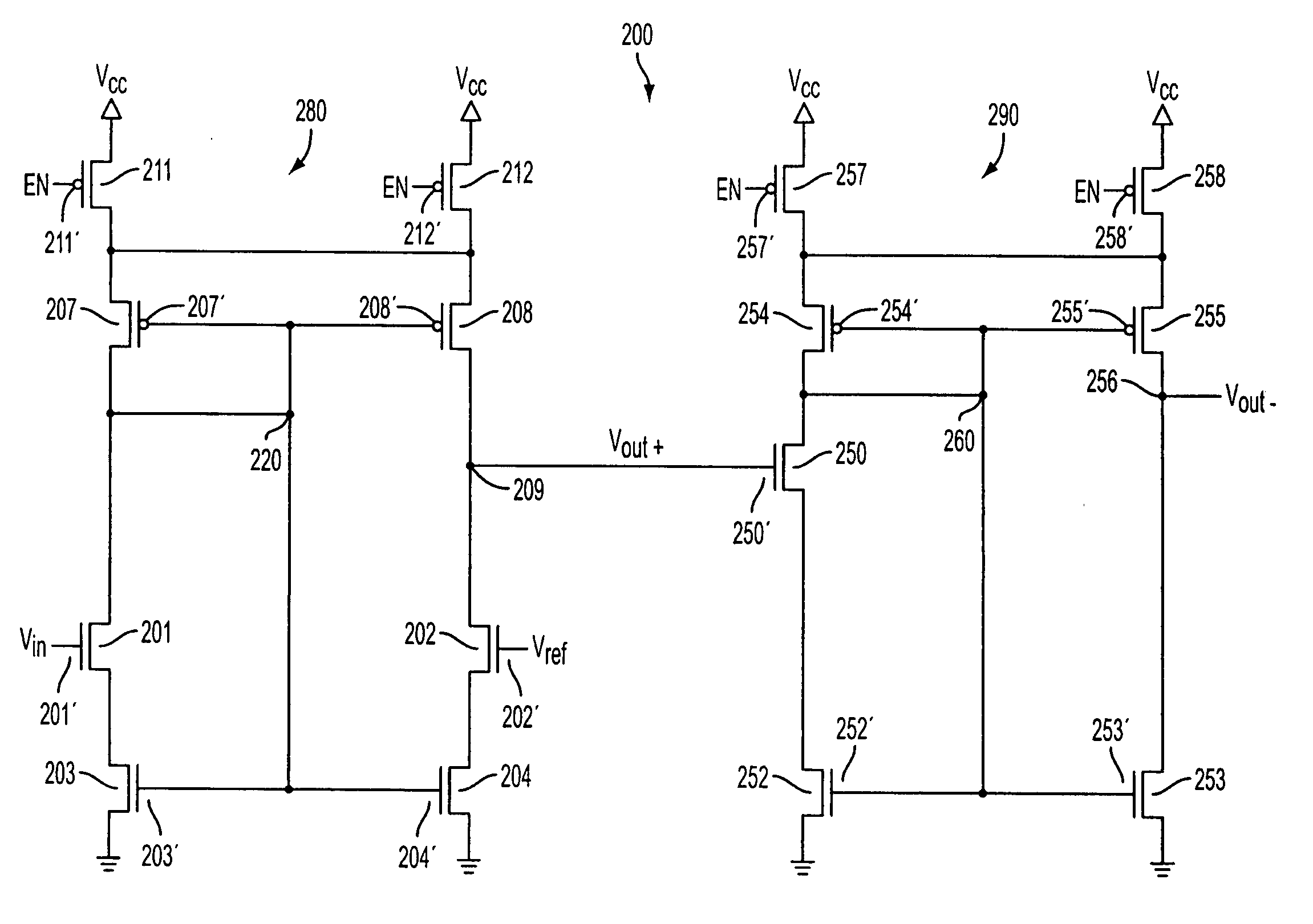
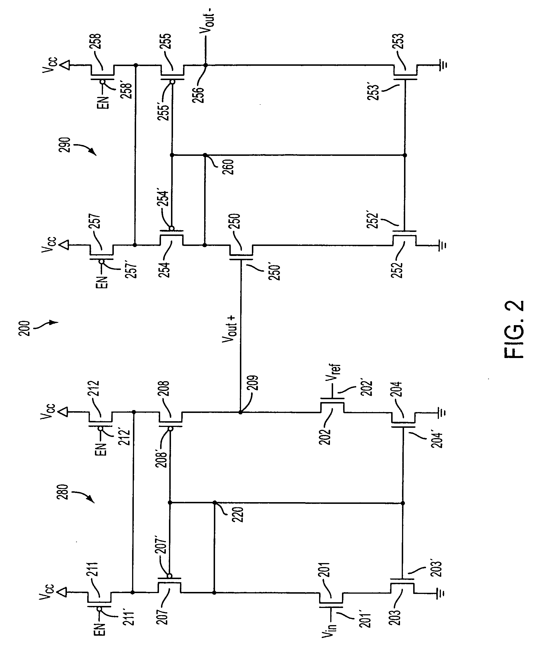
[0021] Now referring to the figures, where like numerals designate like elements, FIG. 3 illustrates a circuit diagram of an input buffer 300 of the invention, which includes a first stage ci...


PUM


Abstract

An input buffer includes a first stage for receiving an input signal and having a first pair of complementary output signals, the first stage including an input circuit for receiving the input signal, an output circuit for generating the first pair of complementary output signals based on the input signal, a resistance feedback circuit connected to the first pair of complementary output signals and generating a feedback signal, and a common mode circuit for balancing the complementary outputs based on the feedback signal.

Description

FIELD OF THE INVENTION [0001] The present invention relates to an input buffer design. BACKGROUND OF THE INVENTION [0002] Input buffers driven with single-ended signals, yet having differential outputs can be used, for instance, in signal processing where a signal must be transmitted over long distances with minimal signal degradation due to interference from external sources, i.e. noise. The differential output signal is produced to be output over two lines as a positive and negative form of the input signal. Because any signal noise would most likely affect both lines equally, the noise component may be removed from the signal by subtracting the two outputs. [0003] One problem associated with input buffers driven with single-ended input signals is ensuring a balanced differential output. FIG. 1A illustrates a schematic of a conventional input buffer 100 depicted as an operational amplifier. The amplifier 100 receives an input voltage Vin at a positive terminal and a reference volt...

Claims


Application Information

Patent Timeline
IPC IPC(8): H03F3/45
CPCH03F3/45183H03F3/45475H03F2203/45624H03F2203/45221H03F2203/45528H03F2203/45166
Inventor STAPLES, TRAVISBAKER, JACOB
Owner MICRON TECH INC
Why Eureka
Try Eureka