Edge-lit backlight having light recycling cavity with concave transflector

a technology of concave transflector and light recycling cavity, which is applied in the field of backlights, can solve the problems of difficult to effectively mix light sources that produce different colors, particularly in the uniformity of illumination,

Inactive Publication Date: 2007-03-01
3M INNOVATIVE PROPERTIES CO
View PDF99 Cites 97 Cited by
  • Summary
  • Abstract
  • Description
  • Claims
  • Application Information

AI Technical Summary

Benefits of technology

[0006] In one aspect, the present disclosure provides an edge-lit backlight having an output area. The edge-lit backlight includes a back reflector facing the output area of the backlight, and a transflector that partially transmits and partially reflects incident light, the transflector being shaped to form at least one concave structure facing the back reflector to provide one or more recycling cavities therebetween. The one or more recycling cavities substantially fill the output area of the backlight. The backlight further includes at least one light source positioned adjacent a first edge of the backlight. The at least one light source is operable to inject light into the one or more recycling cavities through an input surface of the one or more recycling cavities, where the input surface is substantially orthogonal to the output area of the backlight. The at least one concave structure converges with the back reflector in a direction distal from the input surface.
[0007] In another aspect, the present disclosure provides a display system that includes a display panel having an illumination side and a viewing side, and an edge-lit backlight disposed on the illumination side of the display panel. The backlight has an output area. The backlight includes a back reflector facing the output area of the backlight, and a transflector that partially transmits and partially reflects incident light, the transflector being shaped to form at least one concave structure facing the back reflector to provide one or more recycling cavities therebetween. The one or more recycling cavities substantially fill the output area of the backlight. The backlight further includes at least one light source positioned adjacent a first edge of the backlight. The at least one light source is operable to inject light into the one or more recycling cavities through an input surface of the one or more recycling cavities, where the input surface is substantially orthogonal to the output area of the backlight. The at least one concave structure converges with the back reflector in a direction distal from the input surface.
[0008] In another aspect, the present disclosure provides an edge-lit backlight having an output area. The backlight includes a back reflector, and transflector means for partially transmitting and partially reflecting incident light. The transflector means includes at least one concave structure facing the back reflector to provide one or more recycling cavities therebetween, where the one or more recycling cavities substantially fill the output area of the panel. The backlight also includes light source means positioned adjacent a first edge of the backlight for injecting light into the one or more recycling cavities through an input surface of the one or more recycling cavities, where the input surface is substantially orthogonal to the output area of the backlight. The at least one concave structure converges with the back reflector in a direction distal from the input surface.
[0009] The above summary of the present disclosure is not intended to describe each disclosed embodiment or every implementation of the present disclosure. The Figures and Detailed Description that follow more particularly exemplify illustrative embodiments.

Problems solved by technology

Illuminance uniformity is particularly a problem when the light sources used at the edge of the backlight are point sources, e.g., light emitting diodes (LEDs).
Because the human eye more easily discerns variations in color than in brightness, it can be difficult to effectively mix light sources that produce different colors to provide white illumination light to the display.

Method used


Image

  • Edge-lit backlight having light recycling cavity with concave transflector
  • Edge-lit backlight having light recycling cavity with concave transflector
  • Edge-lit backlight having light recycling cavity with concave transflector

Examples


Embodiment Construction

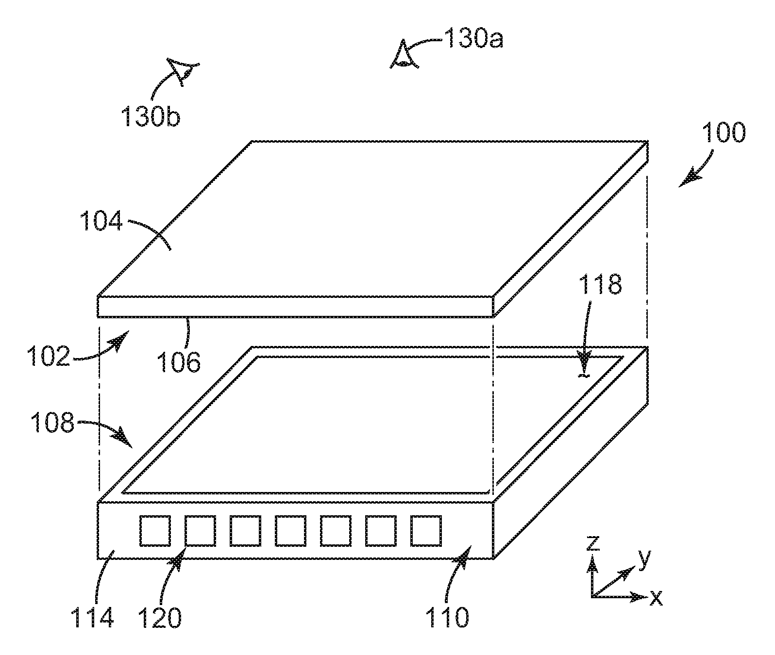
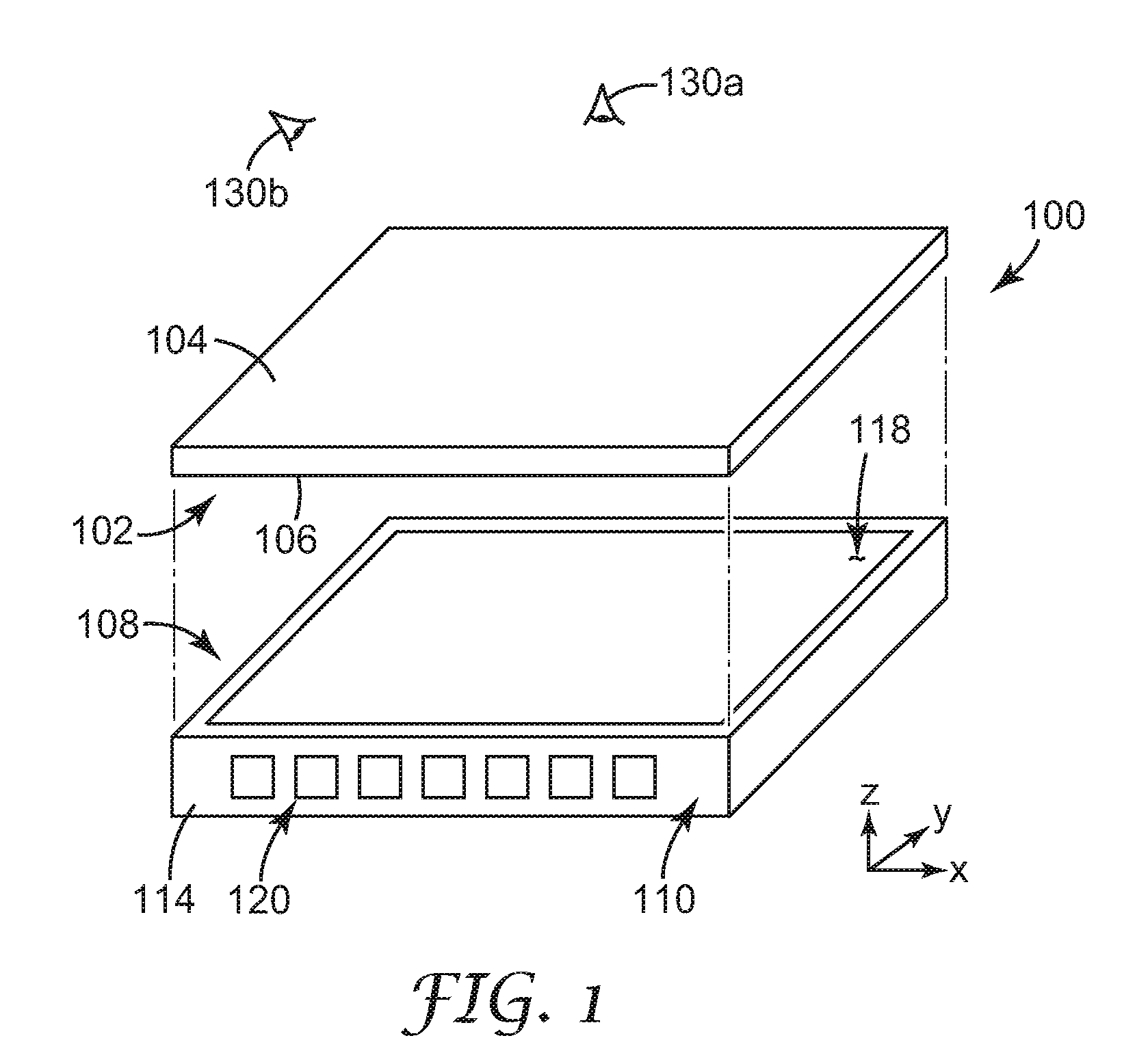
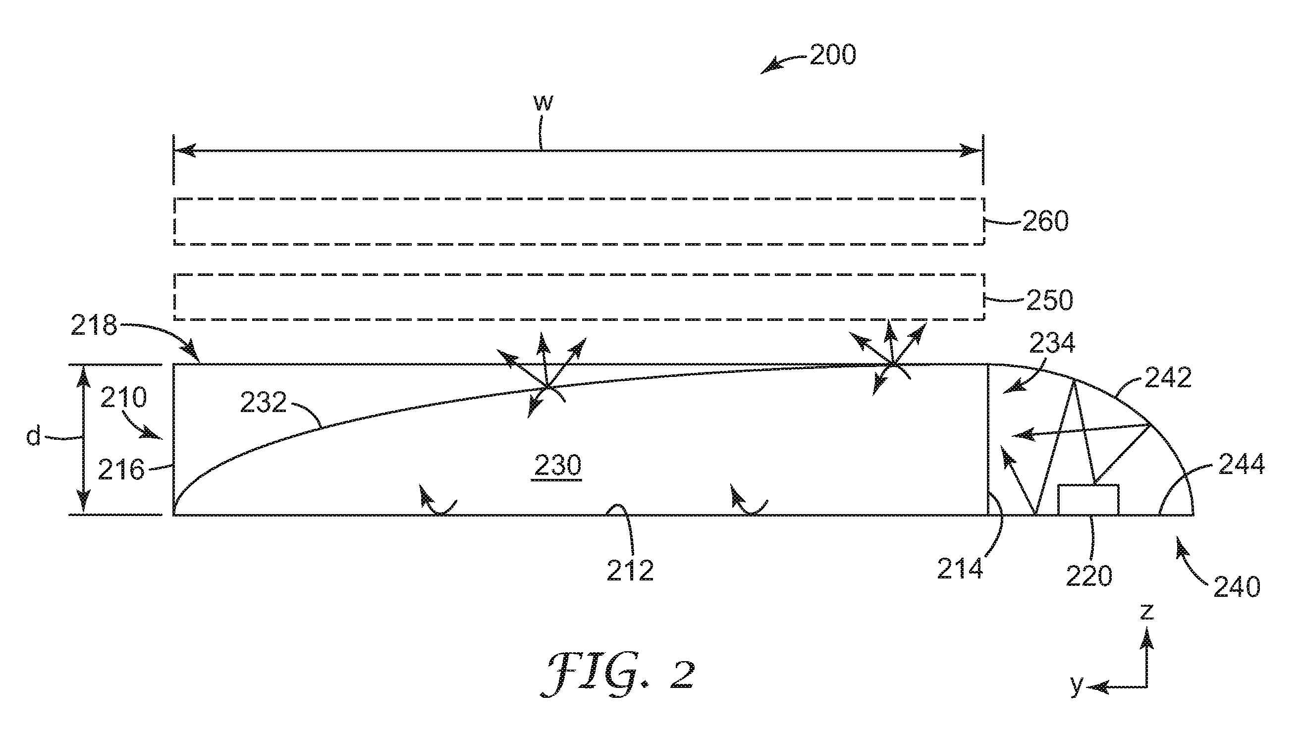
[0018] The present disclosure describes edge-lit backlights that include a back reflector and a transflector that partially transmits and partially reflects incident light. The transflector is shaped to form at least one concave structure facing the back reflector to provide one or more recycling cavities therebetween. At least one light source, and in some cases an array of light sources, is positioned adjacent an edge of the backlight to inject light into each recycling cavity. Advantageously, conventional packaged or unpackaged LEDs can be used as light sources.

[0019] Edge-lit backlights are well known for small displays such as those found in cellular phones, personal digital assistants, and laptop computers. Typically, such backlights use a solid lightguide to uniformly redistribute the light (from one or more light sources located at one or more edges of the display) across the area of the display panel. Solid lightguides work well for small displays; however, they do not sca...


PUM


Abstract

An edge-lit backlight having a light recycling cavity with concave transflector is disclosed. The edge-lit backlight has an output area and includes a back reflector facing the output area of the backlight. The backlight further includes a transflector that partially transmits and partially reflects incident light, the transflector being shaped to form a concave structure facing the back reflector to provide one or more recycling cavities therebetween, where the one or more recycling cavities substantially fill the output area of the backlight. The backlight further includes at least one light source positioned adjacent a first edge of the backlight. The at least one light source is operable to inject light into the one or more recycling cavities through an input surface of the one or more recycling cavities, where the input surface is substantially orthogonal to the output area, and where the at least one concave structure converges with the back reflector in a direction distal from the input surface.

Description

CROSS REFERENCE TO RELATED APPLICATION [0001] This application claims the benefit of U.S. Provisional Patent Application No. 60 / 711,520, filed Aug. 27, 2005, the disclosure of which is incorporated by reference herein in its entirety.FIELD OF THE DISCLOSURE [0002] The present disclosure relates to backlights, particularly edge-lit backlights, as well as to components used in backlights, systems that use backlights, and methods of making and using backlights. The disclosure is particularly well suited to backlights used in liquid crystal display (LCD) devices and similar displays, as well as to backlights that utilize LEDs as a source of illumination. BACKGROUND [0003] Recent years have seen tremendous growth in the number and variety of display devices available to the public. Computers (whether desktop, laptop, or notebook), personal digital assistants (PDAs), mobile phones, and thin LCD TVs are but a few examples. Although some of these devices can use ordinary ambient light to vi...

Claims


Application Information

Patent Timeline
Patent Type & Authority Applications(United States)
IPC IPC(8): F21V7/04H01L33/54
CPCG02B6/0021G02B6/0031H01L33/54G02B6/0096G02B6/0055H01L2224/48091H01L2224/48247H01L2224/48257H01L2924/1815H01L2924/00014G02F1/1335
Inventor SCHARDT, CRAIG R.THOMPSON, D. SCOTTWHEATLEY, JOHN A.LU, DONG
Owner 3M INNOVATIVE PROPERTIES CO
Why Eureka
Try Eureka