Q-modulation semiconductor laser

A laser and semiconductor technology, applied in the direction of semiconductor lasers, lasers, laser parts, etc., can solve the problems of difficult integration, wavelength chirping, and complicated production, and achieve the effect of high extinction ratio, low wavelength chirp, and high speed.

Inactive Publication Date: 2006-09-27
何建军
View PDF4 Cites 20 Cited by
  • Summary
  • Abstract
  • Description
  • Claims
  • Application Information

AI Technical Summary

Problems solved by technology

[0008] The purpose of the present invention is to address the deficiencies in the prior art, and propose a Q-modulated semiconductor laser, which solves t

Method used


Image

  • Q-modulation semiconductor laser
  • Q-modulation semiconductor laser
  • Q-modulation semiconductor laser

Examples


Embodiment approach

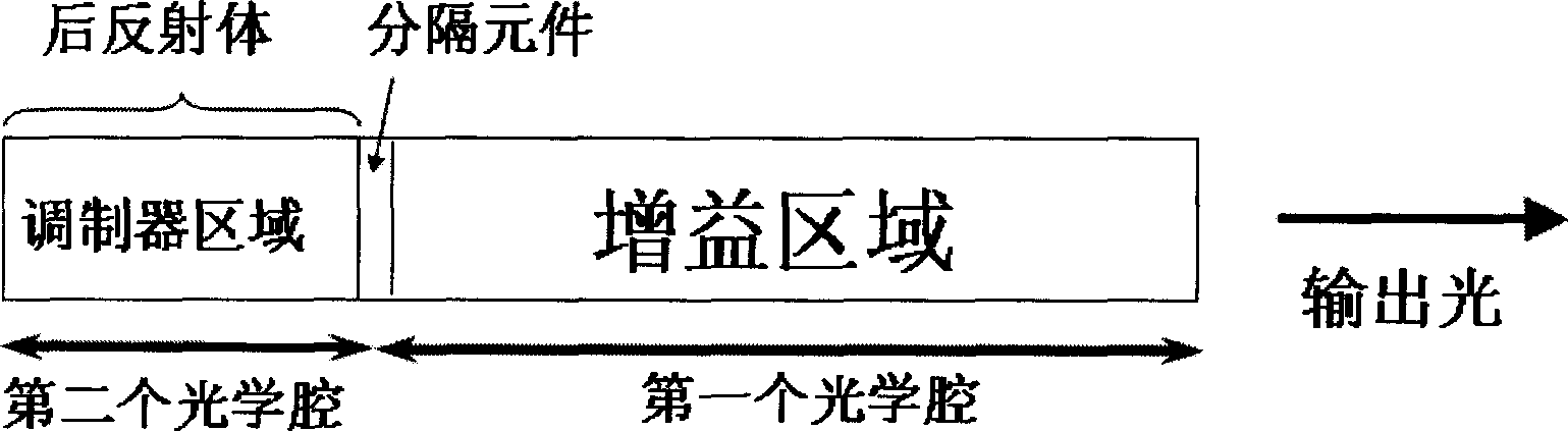
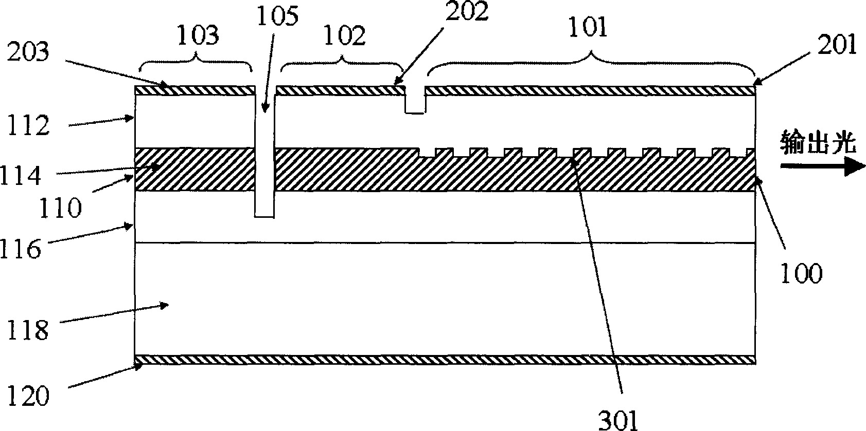
[0082] FIG. 13( a ) shows a third embodiment of the present invention, where the Q-modulator is integrated with a Fabry-Perot laser, which includes a gain region 101 and a modulator region 103 . Each zone has a separate top electrode (201 and 203 respectively) and a common ground electrode 120 at the bottom. The modulator region 103 and the gain region 102 are separated by a separation element 105, here a deep vertically etched air slot through the waveguide core. In addition, as shown in Fig. 13(b), we can also integrate a mode selector 108 composed of one or more Fabry-Perot cavities on the same chip to obtain single-mode operation of the laser. The mode selector 108 acts as an optical filter and can be separated from the gain region 101 by a separation element 107 (here another deeply etched air slot). An upper electrode 208 can be deposited on top of the mode selector region to inject current to make the underlying waveguide substantially transparent and change its refrac...


PUM


Abstract

This invention discloses a Q-modulation semiconductor laser, which includes the first optics cavity and the second cavity, wherein the first optics cavity is a resonator with gain zone, the second optics cavity is a resonator with modulation zone; and the second optics cavity couples with the first optics cavity by the separation element reflected by a section, and the second optics cavity is used as the back reflector of the laser; and the modulation zone's absorption coefficient is modulated by a electrolytic method, which affects the back reflector's reflection rate and laser Q value, which changes the threshold value and output energy of the laser transmitting. The Q-modulation semiconductor laser in this invention has many advantages such as high integration, high speed, high delustring ratio, lower wavelength chirp.

Description

technical field [0001] The present invention relates to semiconductor lasers and modulators, and more particularly to a Q-modulated semiconductor laser monolithically integrated with a Q-modulator that utilizes current injection or electroabsorption effects to change the reflectivity of the laser rear reflector. Background technique [0002] High-speed semiconductor lasers and modulators are key components of today's fiber optic communication systems. The rapid increase in Internet traffic requires these optics to handle ever greater bit rates. It is the simplest method to directly modulate the optical signal intensity by changing the bias current of the laser, and it does not require an external modulator. However, a directly modulated laser has fundamental speed limitations and also exhibits transient oscillations with a frequency equal to its relaxation oscillation frequency. Wavelength chirp is another problem with directly modulated lasers. When the input driving cur...

Claims


Application Information

Patent Timeline
IPC IPC(8): H01S5/00H01S5/10H01S5/06
Inventor 何建军
Owner 何建军
Why Eureka
Try Eureka