Imaging device equipped with flash unit

a technology of imaging device and flash unit, which is applied in the direction of instruments, television systems, and control of exposure, etc., can solve the problems of overexposure of the main subject, chroma clip of highlight, and ambient light amount integrated by the external sensor not always indicating the correct status of ambient light applied to the main subj

Active Publication Date: 2007-03-01
FUJIFILM HLDG CORP +1
View PDF8 Cites 33 Cited by
  • Summary
  • Abstract
  • Description
  • Claims
  • Application Information

AI Technical Summary

Problems solved by technology

However, since a light receiving area of the external sensor corresponds to all of a shooting frame (predetermined angle of view) or to a central part thereof, the ambient-light amount integrated by the external sensor does not always indicate a correct status of the ambient light applied to a main subject, depending on a location and a size of the main subject taken within the frame.
Thus, when the ambient light applied to the main subject is bright, overexposure of the main subject occurs.
As a result, there arises a problem in that chroma clip of highlight is caused.
As a result, there arises a problem in that the main subject is darkly taken.

Method used


Image

  • Imaging device equipped with flash unit
  • Imaging device equipped with flash unit
  • Imaging device equipped with flash unit

Examples


Embodiment Construction

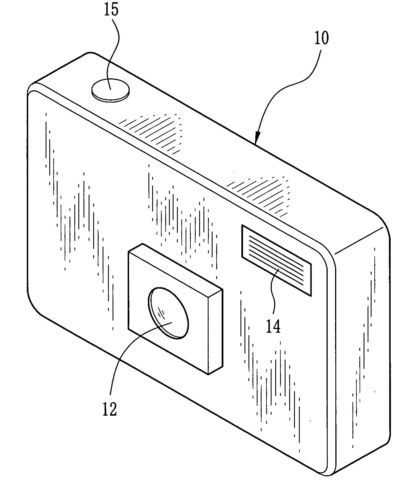
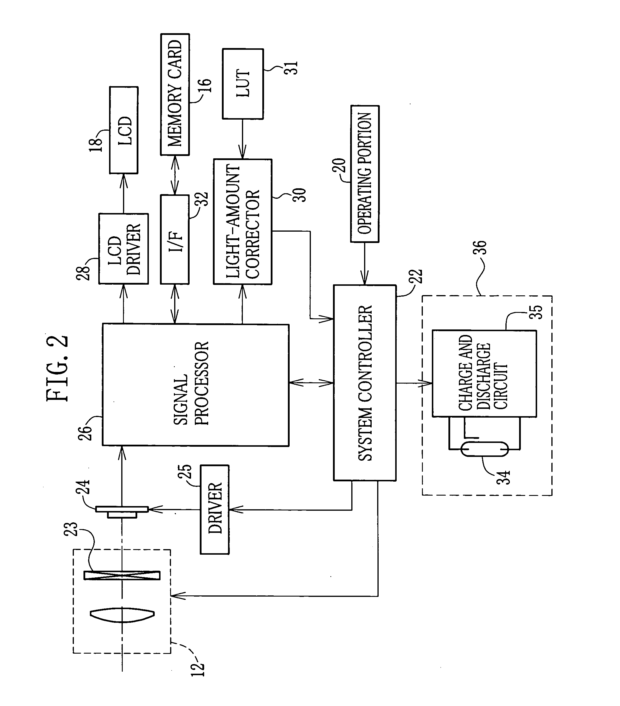
[0015] In FIG. 1 showing an electronic still camera 10 of the present invention, which is regarded as an imaging device, a front side thereof is provided with a taking lens unit 12 and a flash window 14 for radiating flash light toward a subject. A release button 15 is disposed on a top side of the electronic still camera 10. By depressing the release button 15, a still image of one frame is taken. Digital data obtained by shooting is recorded in a memory card 16 (see FIG. 2) contained in the electronic still camera 10.

[0016] A rear side of the electronic still camera 10 is provided with an LCD (Liquid Crystal Display) 18 (see FIG. 2), operating buttons for performing various kinds of setting of the electronic still camera 10, and so forth. By handling the operating buttons while the LCD 18 displays a menu, it is possible to change a shooting mode and a reproducing mode and to select a flash mode. As to the flash mode, for example, it is possible to select a low-brightness automati...


PUM


Abstract

Upon depression of a release button, pre-shooting is performed before regular shooting. In the pre-shooting, flash of a predetermined amount is emitted and exposure of an image sensor is performed. A shooting frame is divided into small areas. As to each of the small areas, subject brightness of pre-emission and subject brightness of non-emission are detected to calculate a difference between them. The small area having the maximum difference is selected as a main-subject area. The brightness of the non-emission of the selected small area, which is the brightness of an ambient light applied to the main subject, is set as reference brightness. A correction amount of the flash amount of the regular shooting corresponding to the reference brightness is derived with reference to an LUT. In the regular shooting, regular emission is performed during a regular-emission time corresponding to the collected flash amount.

Description

FIELD OF THE INVENTION [0001] The present invention relates to an imaging device equipped with a flash unit. BACKGROUND OF THE INVENTION [0002] Imaging devices such as an electronic still camera, a camera-equipped cell-phone and so forth are widely used. This kind of the imaging device takes a subject image with an image sensor of a CCD image sensor and so forth, and records obtained image data in a recording medium of a memory card and so forth. Some of the imaging devices are equipped with a flash unit (see Japanese Patent Laid-Open Publication No. 6-303504, for instance). The imaging device described in this Publication No. 6-303504 controls a flash-light amount in accordance with ambient light, which is applied to a subject, to prevent overexposure at a time when flash light is applied to the subject in addition to the ambient light. [0003] The imaging device described in the above-noted Publication No. 6-303504 integrates an ambient-light amount with an external sensor. When th...

Claims


Application Information

Patent Timeline
Patent Type & Authority Applications(United States)
IPC IPC(8): G03B15/03G03B7/16G03B15/05H04N5/238H04N101/00
CPCG03B7/16G03B15/05H04N5/2354H04N5/2351G03B2215/0503H04N23/71H04N23/74
Inventor NOSE, SYUJIIIMURA, NORIFUMI
Owner FUJIFILM HLDG CORP
Why Eureka
Try Eureka