Imaging apparatus and imaging control method for focusing by determining a focusing position

a technology of imaging control and focusing position, which is applied in the direction of color television details, instruments, television systems, etc., can solve the problems of focusing position being misdetected, focusing position cannot be accurately determined, and out of focus

Active Publication Date: 2012-08-14
FUJIFILM CORP
View PDF14 Cites 35 Cited by
  • Summary
  • Abstract
  • Description
  • Claims
  • Application Information

AI Technical Summary

Benefits of technology

[0013]In view of the above circumstances, the presently disclosed subject matter has been made, and an object of the presently disclosed subject matter is to provide an imaging apparatus and an imaging control method capable of focusing by determining a focusing position in an accurate and easy manner even in a scene in which there is a point light source.
[0031]According to the above, if detection is made at a plurality of lens positions that an average value of pixel values or intensity values is greater than the threshold, a determination is made that there is a point light source. Therefore, focusing accuracy can be further improved by surely preventing a misdetection of a point light source. Moreover, saturation detection is made at a lens position in which a contrast evaluation value is calculated. Therefore, a point light source can be surely detected at a lens position in which the point light source influences the evaluation value, and thus focusing accuracy can be improved.

Problems solved by technology

However, if the focusing area is small, it is easier to be influenced by a point light source (a light source the size of which is), thus causing a problem in that the focusing position cannot be determined accurately.
This causes a problem in that the focusing position is mis-detected and an out of focus occurs.

Method used


Image

  • Imaging apparatus and imaging control method for focusing by determining a focusing position
  • Imaging apparatus and imaging control method for focusing by determining a focusing position
  • Imaging apparatus and imaging control method for focusing by determining a focusing position

Examples


first embodiment

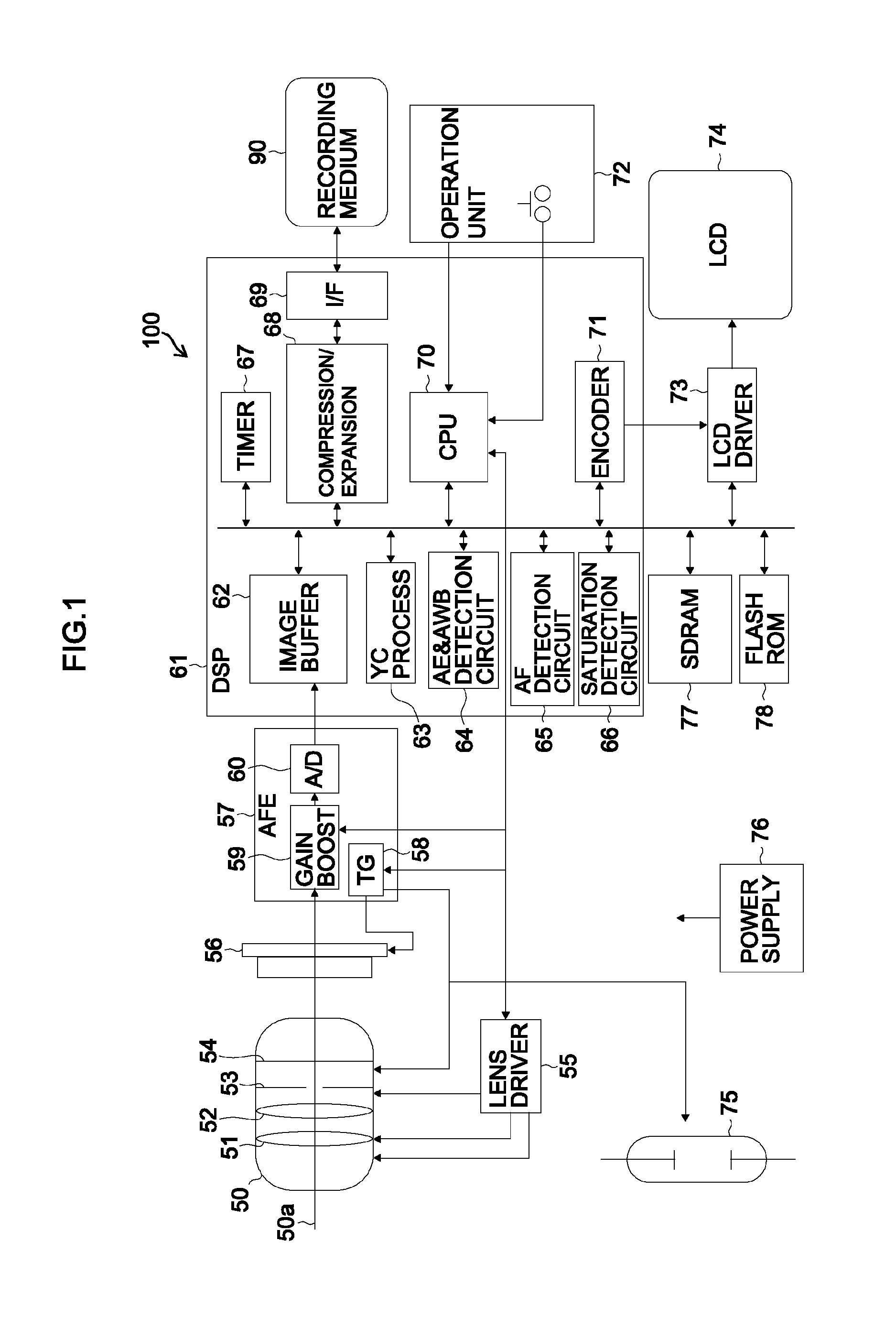
[0058]FIG. 1 is a block diagram illustrating an entire configuration of a digital camera 100 as an example of an imaging apparatus according to a first embodiment of the presently disclosed subject matter.

[0059]An imaging optical system 50 is configured to include a zoom lens 51, a focus lens 52, an iris 53, and a mechanical shutter 54. A lens driver 55 is configured to include a motor and a drive circuit and drives the zoom lens 51, the focus lens 52, and the iris 53 of the imaging optical system 50. A CCD (Charge Coupled Device) image sensor 56 images an object image focused by the imaging optical system 50. The zoom lens 51 is driven by the lens driver 55 and moves along an optical axis 50a of the imaging optical system 50. Thereby, an object image focused on a light receiving surface of the CCD image sensor 56 is optically variably magnified. The focus lens 52 is driven by the lens driver 55 and moves along the optical axis 50a of the imaging optical system 50. Thereby, focusing...

second embodiment

[0105]Now, the second embodiment will be described. The following description focuses only on a portion different from that of the first embodiment. The present embodiment is different in the AF search area setting from the first embodiment.

[0106]FIG. 11 illustrates a saturation detection area 231 and FIG. 12 illustrates AF search areas 241 and 242. In the AF search area setting (in step S35 of FIG. 4), a first AF search area 241 is set in the center of the image area 200 as illustrated in FIG. 12. The second AF search area 242 is larger in size than the first AF search area 241 and is not overlapped with the first AF search area 241. According to the present embodiment, the second AF search area 242 is arranged around the first AF search area 241.

[0107]Note that the saturation detection area 231 illustrated in FIG. 11 has the same position and size as the first AF search area 241. However, the size of the saturation detection area 231 may be slightly larger than the size of the fir...

third embodiment

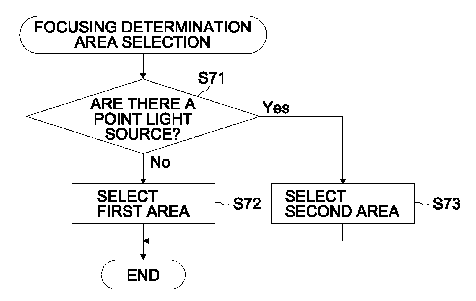
[0109]Now, the third embodiment will be described. The following description focuses only on a portion different from that of the first embodiment. The present embodiment is different from the first embodiment in the saturation detection area setting, the AF search area setting, the point light source detection process, and the focusing determination area selection.

[0110]FIG. 13 illustrates an example of a saturation detection area arrangement, and FIG. 14 illustrates an example of an AF search area arrangement.

[0111]In the saturation detection area setting (in step S32 of FIG. 4), a 7×7 matrix of divided areas (numbers 0 to 48) arranged two-dimensionally in a vertical direction and a horizontal direction in the image area 200 is set as a saturation detection area 251 as illustrated in FIG. 13. That is, a plurality of saturation detection areas 251 not overlapped to each other with respect to the imaging image is set. The size of each of the plurality of divided areas is the same. N...


PUM


Abstract

An imaging apparatus includes: an imaging optical system including a focus lens; an imaging element generates an image indicating an object image; a lens drive device which moves the focus lens along an optical axis direction of the imaging optical system; an evaluation value calculation device which calculates an evaluation value of a contrast for each of a plurality of evaluation value calculation areas while moving the focus lens; a point light source presence / absence determination device which determines a presence or absence of a point light source in a specific region of the image; an area selection device which selects a focusing determination area based on the presence or absence of the point light source; and a focusing control device which determines the focusing position of the focus lens based on the evaluation value in the focusing determination area and moves the focus lens to the focusing position.

Description

BACKGROUND OF THE INVENTION[0001]1. Field of the Invention[0002]The presently disclosed subject matter relates to an imaging apparatus and an imaging control method capable of focusing by determining a focusing position in an accurate and easy manner even in a scene in which there is a point light source.[0003]2. Description of the Related Art[0004]Japanese Patent No. 3296687 discloses a configuration in which when an AF (automatic focus adjustment process) control is performed, the area of a high-intensity portion is detected in a focusing area; the intensity of the high-intensity portion is weighted in such a manner that the larger the area of the high-intensity portion, the smaller the weight; and the weighted intensity of the high-intensity portion is used as a focus evaluation value.[0005]Japanese Patent Application Laid-Open No. 2006-215391 discloses a configuration in which the pixel area (saturation area) in which the intensity level is saturated in a focusing area is detect...

Claims


Application Information

Patent Timeline
Patent Type & Authority Patents(United States)
IPC IPC(8): H04N5/232G03B13/36
CPCH04N5/23212H04N23/675H04N23/673
Inventor UCHIDA, AKIHIRO
Owner FUJIFILM CORP
Why Eureka
Try Eureka