Laser differential confocal curvature radius measuring method and device

A technology of differential confocal and radius of curvature, which is applied in the direction of measuring devices, optical devices, instruments, etc., can solve the problem of unsatisfactory high-precision testing of the radius of curvature of spherical elements, achieve strong anti-environmental interference, ensure measurement accuracy, Effect of improved measurement accuracy

Active Publication Date: 2019-01-25
BEIJING INSTITUTE OF TECHNOLOGYGY
View PDF5 Cites 15 Cited by
  • Summary
  • Abstract
  • Description
  • Claims
  • Application Information

AI Technical Summary

Problems solved by technology

[0012] The purpose of the present invention is to solve the problem of unsatisfactory high-precision measurement of the radius of curvature of spherical elements, and to provide a method and device for measuring the radius of curvature of the laser differential confocal. Pupil differential confocal detection system for detection, thereby realizing precise focusing and high-precision measurement of curvature radius

Method used


Image

  • Laser differential confocal curvature radius measuring method and device
  • Laser differential confocal curvature radius measuring method and device
  • Laser differential confocal curvature radius measuring method and device

Examples


Embodiment 1

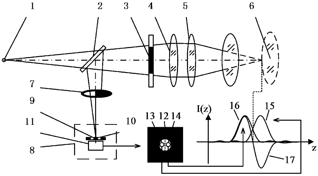
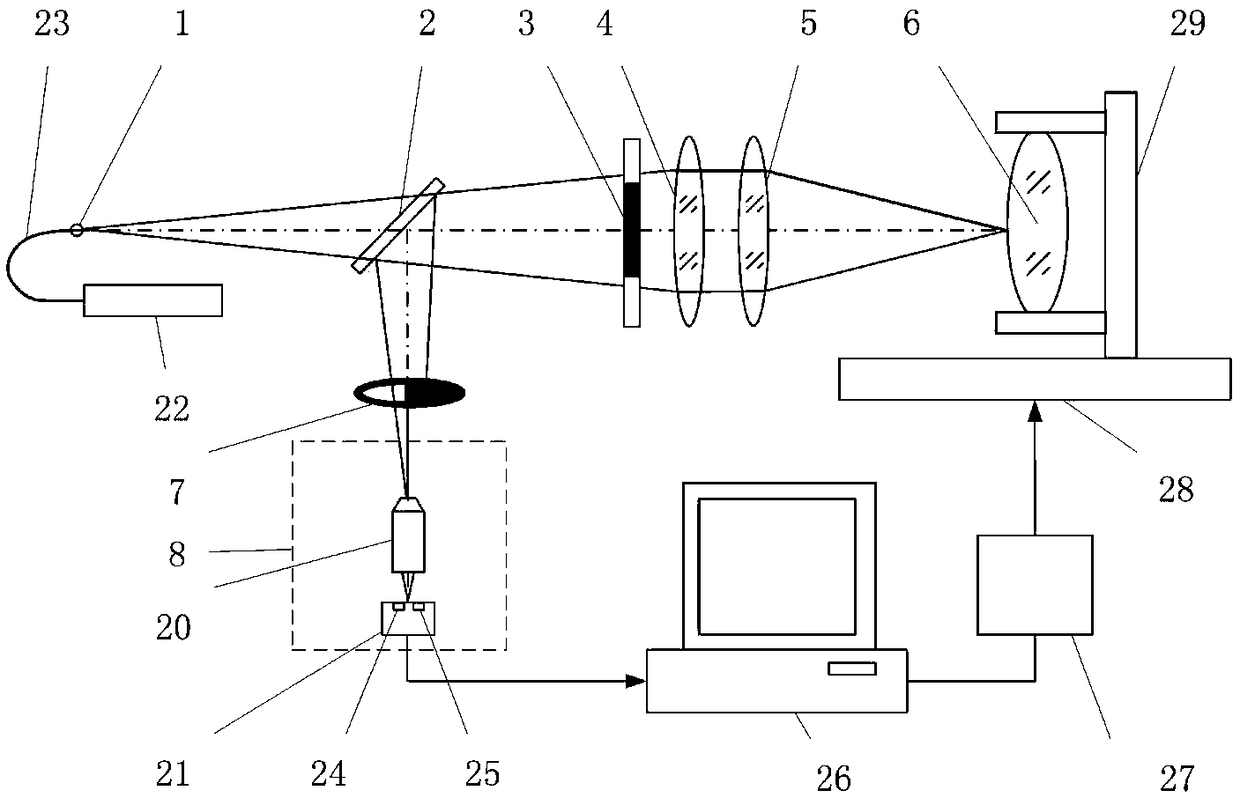
[0045] Such as image 3 As shown, a laser differential confocal radius of curvature measurement device includes a laser 22, an optical fiber 23, and a point light source 1, which are sequentially placed in the beam splitter 2, annular pupil 3, and collimating lens in the direction of the light emitted by the point light source 1. 4 and converging lens 5, also comprise the D-shaped rear pupil 7 that is placed in beam splitter 2 reflection directions and the split pupil differential confocal detection system 8 that is made of microscopic objective lens 20 and CCD21; Main control computer 26 and motor The drive system 27 is connected so that it drives the linear guide rail 28 to drive the measured element 6 to scan along the optical axis.

[0046] When the device is used to measure the radius of curvature of the lens surface, the split pupil differential confocal detection system 8 in the system is used to locate the apex and the center of the sphere of the surface of the measure...

Embodiment 2

[0056] Such as Figure 4 As shown, a laser differential confocal radius of curvature measuring device, which is compatible with image 3 The difference of the rear split pupil differential confocal radius of curvature measuring device in the embodiment is that the rear pupil is replaced by a D-shaped rear pupil 7 with a circular rear pupil 30 .

[0057] The measurement steps of the device are the same as in Example 1.


PUM


Abstract

The invention relates to a laser differential confocal curvature radius measuring method and a laser differential confocal curvature radius measuring device, which belong to the technical field of optical precision measurement. The laser differential confocal curvature radius measuring method utilizes a post-positioned pupil to block half of a measuring beam, uses a light splitting pupil differential confocal detection system for detecting a measuring beam to obtain a differential confocal response curve, and utilizes an absolute zero point of the differential confocal response curve to perform precise focus fixation on a surface vertex position and a sphere center position of a spherical element separately, so as to obtain a curvature radius of the element. According to the laser differential confocal curvature radius measuring method and the laser differential confocal curvature radius measuring device, the post-positioned light splitting pupil laser differential confocal technologyis applied to the high-precision detection of the curvature radius of the spherical element for the first time, the differential confocal focus fixation and curvature radius measurement is realized byusing only one path of detector, the system structure is simple, the assembly and debugging difficulty is reduced, the possible decrease of focus fixation precision caused by replacement of a measured lens is avoided, further the measurement precision is improved; and data near a zero point of the differential confocal response curve is subjected to linear fitting, so as to achieve fast triggering of the focus fixation and measurement, thus the measurement speed and precision as well as the scattering resistance are greatly improved.

Description

technical field [0001] The invention relates to a laser differential confocal radius of curvature measurement method and device, which can be used for non-contact high-precision measurement of the curvature radius of a spherical element and belongs to the technical field of optical precision measurement. Background technique [0002] In optical systems, inertial navigation systems, and aircraft engine transmission systems, spherical elements are one of the most important elements. The radius of curvature of the spherical element is the most critical parameter to determine the overall performance of the element, so it is of great significance to measure the radius of curvature of the spherical element with high precision. [0003] For the measurement of the radius of curvature of a spherical surface, the existing measurement methods are: spherical template method, spherometer method, self-collimation method, interferometer method, knife-edge meter method, Newton ring method, ...

Claims


Application Information

Patent Timeline
Patent Type & Authority Applications(China)
IPC IPC(8): G01B11/255
Inventor 赵维谦邱丽荣杨帅
Owner BEIJING INSTITUTE OF TECHNOLOGYGY
Why Eureka
Try Eureka