
Video display apparatus, video composition delivery apparatus, and system

a video display and video composition technology, applied in the field of video display apparatuses and video composition delivery apparatuses, can solve problems such as complex processing

Inactive Publication Date: 2006-08-03
KK TOSHIBA
View PDF22 Cites 37 Cited by
  • Summary
  • Abstract
  • Description
  • Claims
  • Application Information

AI Technical Summary

Benefits of technology

[0017] According to an aspect of the present invention, there is provided with a video display apparatus comprising: a receiving unit configured to receive a composite video image generated from a plurality of video sources; a display unit configured to display the received composite video image; an area manager configured to store area information pieces; a position specification unit configured to specify a position on the composite video image displayed by the display unit; an area selection unit configured to select an area information piece from the area information pieces stored in the area manager; an area display unit configured to provide information indicating the area represented by the area information piece selected by the area selection unit to the display unit so as to superpose the information on the displayed composite video image; an area change unit configured to change the information; an area information update unit configured to update the area information piece selected by the area selection unit stored in the area manager according to the information obtained after the change; and a control signal transmission unit configured to generate an update control signal containing the area information piece after update, and transmit the update control signal to a generation source of the composite video image.
[0018] According to an aspect of the present invention, there is provided with a video composition delivery apparatus, comprising: a video source receiving unit configured to receive video sources of a composite video image; a layout information manager configured to manage layout information pieces including an identifier identifying the video source, the layout information piece indicating the layout of an image represented by the video source on the composite video image; a composite video generation unit configured to generate the composite video image from the video sources received by the video source receiving unit, by using the layout information pieces; a transmitting unit configured to transmit the generated composite video image to a destination device; a control signal receiving unit configured to receive an update control signal from the destination device, the update control signal containing an area information piece indicating an area on the composite video image; a video manager configured to manage a corresponding relation between the identifier of a video source and a further identifier identifying the area information piece contained in the update control signal; and a layout information update unit configured to update the layout information piece of a video source associated with the further identifier according to the area information piece contained in the update control signal.
[0019] According to an aspect of the present invention, there is provided with a video delivery system comprising a video composition delivery apparatus configured to generate a composite video image from video sources and a video display apparatus configured to receive the composition video image from the video composition delivery apparatus to display the received composition video image: the video display apparatus including; a receiving unit configured to receive the composite video image from the video composition delivery apparatus, a display unit configured to display the received composite video image, an area manager configured to store area information pieces, a position specification unit configured to specify a position on the composite video image displayed by the display unit, an area selection unit configured to select an area information piece indicating an area including the position specified by the position specification unit from the area information pieces stored in the area manager, an area display unit configured to provide information indicating the area represented by the area information piece selected by the area selection unit to the display unit so as to superpose the information on the displayed composite video image, an area change unit configured to change the information provided by the area display unit, an area information update unit configured to update the area information piece selected by the area selection unit according to the information obtained after the change, and a control signal transmission unit configured to generate an update control signal containing the area information piece after update and an first identifier identifying the area information piece after update, and configured to transmit the update control signal to the video composition delivery apparatus, the video composition delivery apparatus including: a video source receiving unit configured to receive video sources, a layout information manager configured to manage layout information pieces including an second identifier identifying the video source, the layout information piece indicating the layout of an image represented by the video source on the composite video image, a composite video generation unit configured to generate the composite video image from the video sources received by the video source receiving unit, by using the layout information pieces, a transmitting unit configured to transmit the generated composite video image to the video display apparatus, a control signal receiving unit configured to receive the update control signal from the video display apparatus, a video manager configured to manage a corresponding relation between the second identifier of a video source and the first identifier, and a layout information update unit configured to update the layout information piece of a video source associated with the first according to the area information piece contained in the update control signal.

Problems solved by technology

In these operations, however, the client does not recognize the window and the rectangular figure itself, but the server recognizes the window and rectangular figure.
In addition, it is necessary to consider processing to be conducted when timing for transmitting a control signal from the client and timing for sending a notice of layout information from the server overlap each other, resulting in complicated processing.

Method used


Image

  • Video display apparatus, video composition delivery apparatus, and system
  • Video display apparatus, video composition delivery apparatus, and system
  • Video display apparatus, video composition delivery apparatus, and system

Examples


first embodiment

[0068] Hereafter, a first embodiment of the present invention will be described with reference to FIGS. 3 to 26.

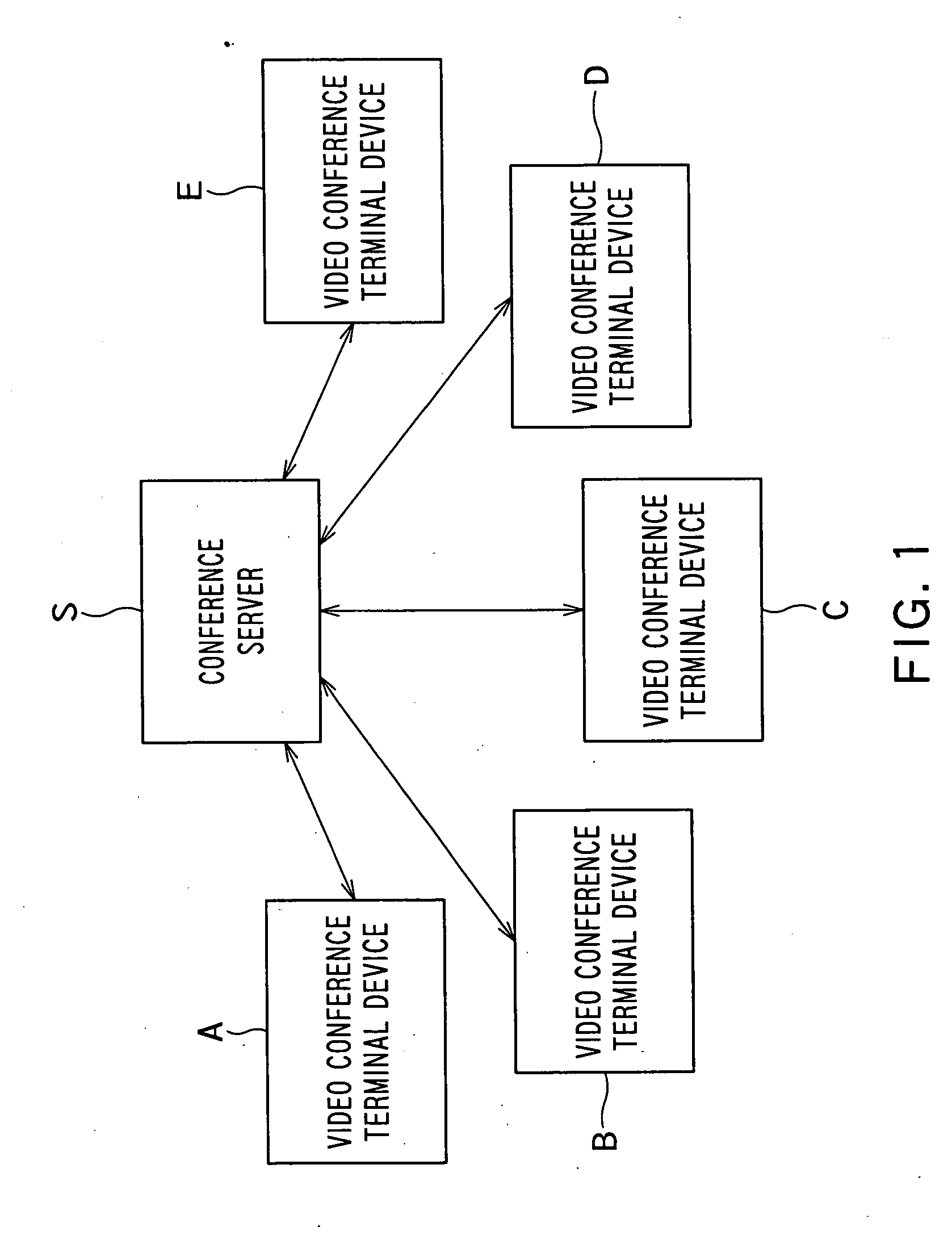
[0069]FIG. 3 shows a system configuration of a multipoint video conference system according to the present invention. FIG. 3 shows an example of the case where video conference is conducted at five points in the multipoint video conference system. The multipoint video conference system includes video conference terminal devices 1, 1B, 1C, 1D and 1E and a conference server 2. The video conference terminal devices 1, 1B, 1C, 1D and 1E are connected to the conference server 2 via a network 3.

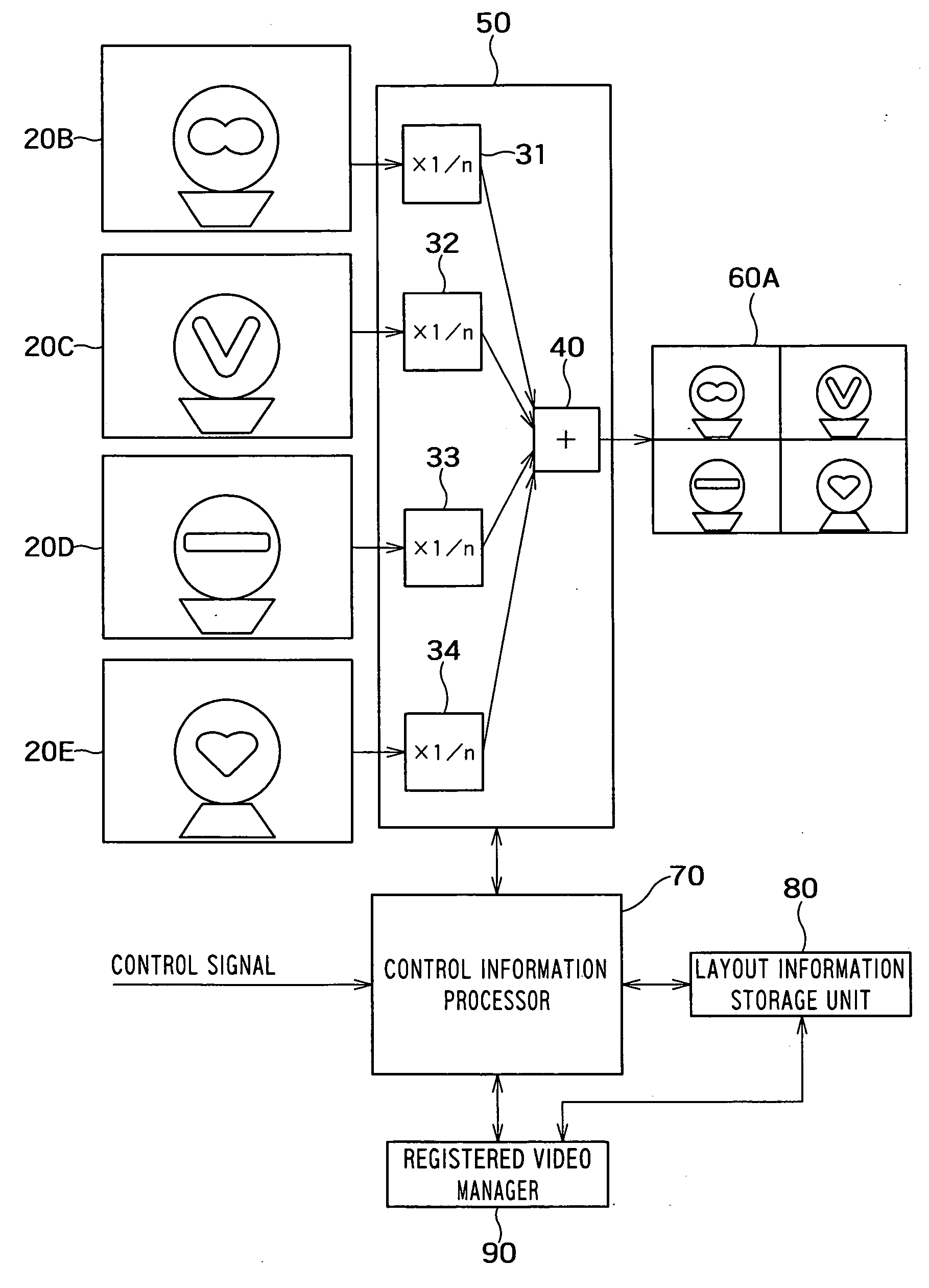
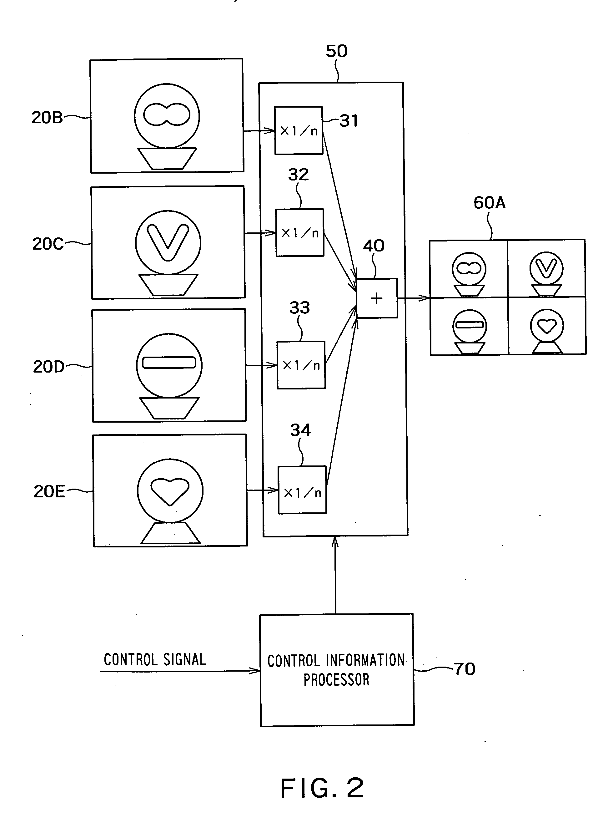
[0070] In the present embodiment, the video conference terminal devices 1B, 1C, 1D and 1E have a function of transmitting video data to the conference server 2 by utilizing communication paths 3-1B, 3-1C, 3-1D and 3-1E, respectively. The conference server 2 has a function of composing video images received from the video conference terminal devices 1B, 1C, 1D and 1E into one video image...

first example

[0096] It is now supposed that the composite video image received from the conference server 2 and displayed in the display area 1000 is shown in FIG. 14A. It is supposed that the area management table managed by the table manager 304 is in the initialized state at this time. The pointer 200 is moved to a position (15, 20) in the display area 1000, and a left click operation is conducted. As a result, for example, a rectangle registration signal rectangle registration signal {1, 0, 0, 100, 100, 1, event B} is generated in the composite video control instruction generator 300, and the area management table is updated as shown in FIG. 14D. The composite video control instruction generator 300 causes a rectangular frame 2000 shown in FIG. 14B to be displayed in the display area 1000, generates a rectangle registration packet shown in FIG. 14C, and transmits the rectangle registration packet to the conference server 2. The conference server 2 creates a composite video image; as for a vi...

second example

[0098]FIG. 15A shows a state in which a predetermined time elapses after the operation described in the first example and the display of the rectangular frame 2000 disappears. As shown in FIG. 15B, the pointer 200 is moved to a certain point in the display area 1000 and a left click operation is conducted. Since the area management table has contents shown in FIG. 14D, rectangular area information is generated in the composite video control instruction generator 300. As a result of generation of the rectangular area information, the composite video control instruction generator 300 displays a rectangular frame 2000 in the display area 1000 as shown in FIG. 15B. Subsequently, the pointer 200 is moved to a lower right-hand vertex of the rectangular frame 2000 shown in FIG. 15B, and left click is conducted in that position. The pointer is moved to a position shown in FIG. 15C. As a result, the “rectangular frame change processing” is executed in the composite video control instruction ...


PUM


Abstract

There is provided with a video display apparatus comprising: a receiving unit configured to receive a composite video image generated from a plurality of video sources; a display unit configured to display the received composite video image; an area manager configured to store area information pieces; a position specification unit configured to specify a position on the composite video image; an area selection unit configured to select an area information piece from the area information pieces; an area display unit configured to provide information indicating the area represented by the selected area information piece to the display unit so as to superpose the information on the displayed composite video image; an area change unit configured to change the information; an area information update unit configured to update the selected area information piece; and a transmission unit configured to transmit an update control signal containing the area information piece after update.

Description

CROSS-REFERENCE TO RELATED APPLICATIONS [0001] This application claims the benefit of priority under 35USC §119 to Japanese Patent Application No. 2005-15929 filed on Jan. 24, 2005, the entire contents of which are incorporated herein by reference. BACKGROUND OF THE INVENTION [0002] 1. Field of the Invention [0003] The present invention relates to a technique for controlling a video image composition processing in a video composition delivery apparatus from a video display apparatus, the video composition delivery apparatus and the video display apparatus being connected to a network. The present invention is used in, for example, a multipoint video conference system utilizing an image composition (video composition) server. [0004] 2. Related Art [0005] It is possible to construct a multipoint video conference system using exchange of video images and voices between information devices capable of transmitting and receiving data via the network. [0006] When constructing a multipoint ...

Claims


Application Information

Patent Timeline
Patent Type & Authority Applications(United States)
IPC IPC(8): H04N7/14
CPCH04N7/147H04N7/152
Inventor KAWAMURA, TAKUYASHIBUYA, NAOHISASUGASAWA, NOBUHIKO
Owner KK TOSHIBA
Learn More