Secure voting system

Inactive Publication Date: 2007-03-08
KYNDRYL INC
View PDF10 Cites 10 Cited by
  • Summary
  • Abstract
  • Description
  • Claims
  • Application Information

AI Technical Summary

Benefits of technology

[0011] Another object of the present invention is to provide improved electronic voting systems, methods and apparatus that permanently stores voting results, ensure that voters securely vote only once, and allow for the validation of voting results.
[0012] It is another object of the present invention to provide improved electronic voting syst

Problems solved by technology

However, many problems exist with these conventional voting machines.
For instance, voting machines making use of paper ballots are undesirably subjected to the destruction and/or physical damage of such ballots, or even the possibility of paper ballots being altered.
Paper ballots are also undesirable since they are subject to incorrect voting results due to voters punching the wrong holes in the ballots and the cumbersome tasks of reading and tabulating voting results for such paper ballots (particularly for write-in votes), in addition to numerous other problems associated with paper balloting.
However, a common problem associated with t

Method used


Image

  • Secure voting system
  • Secure voting system
  • Secure voting system

Examples


Example

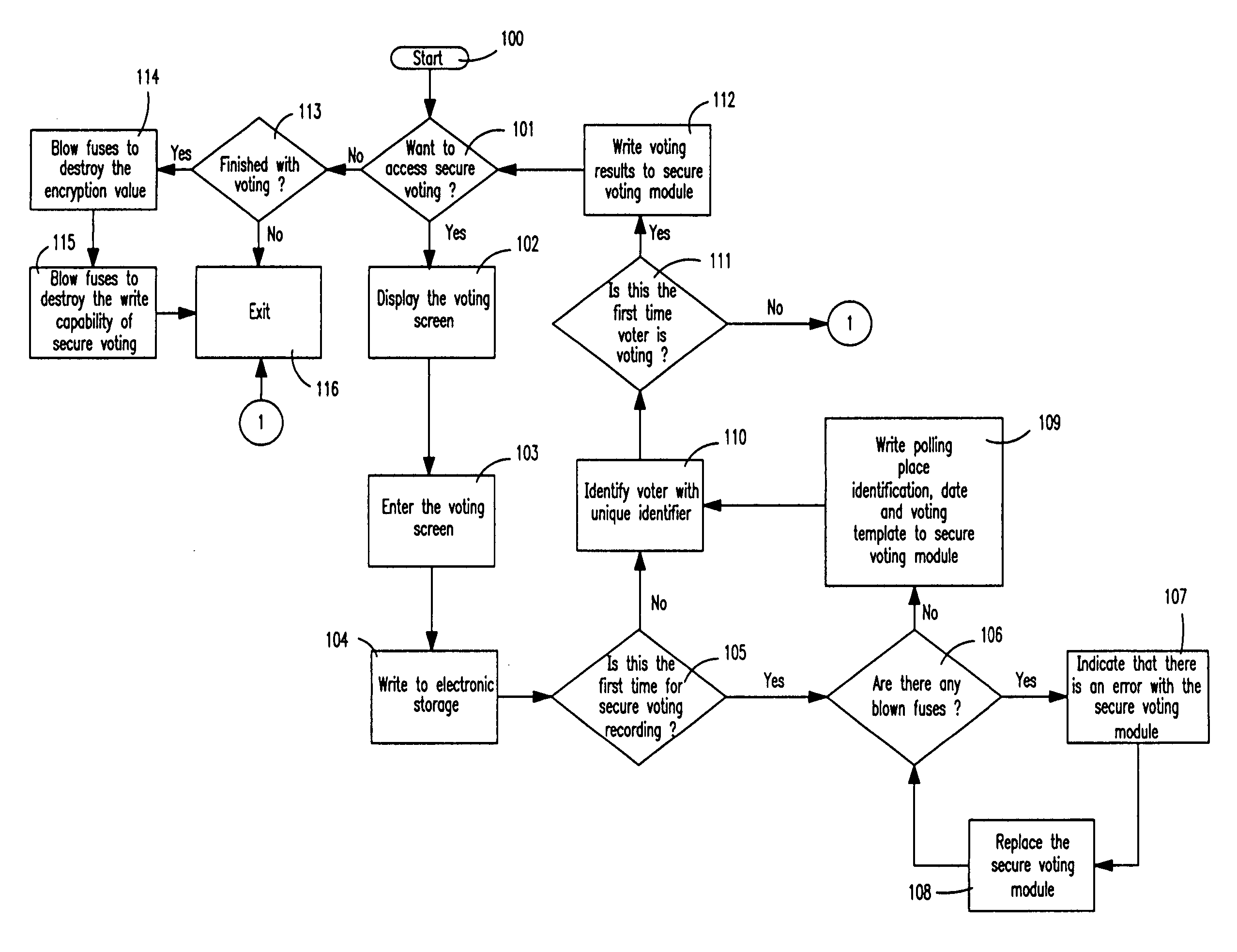
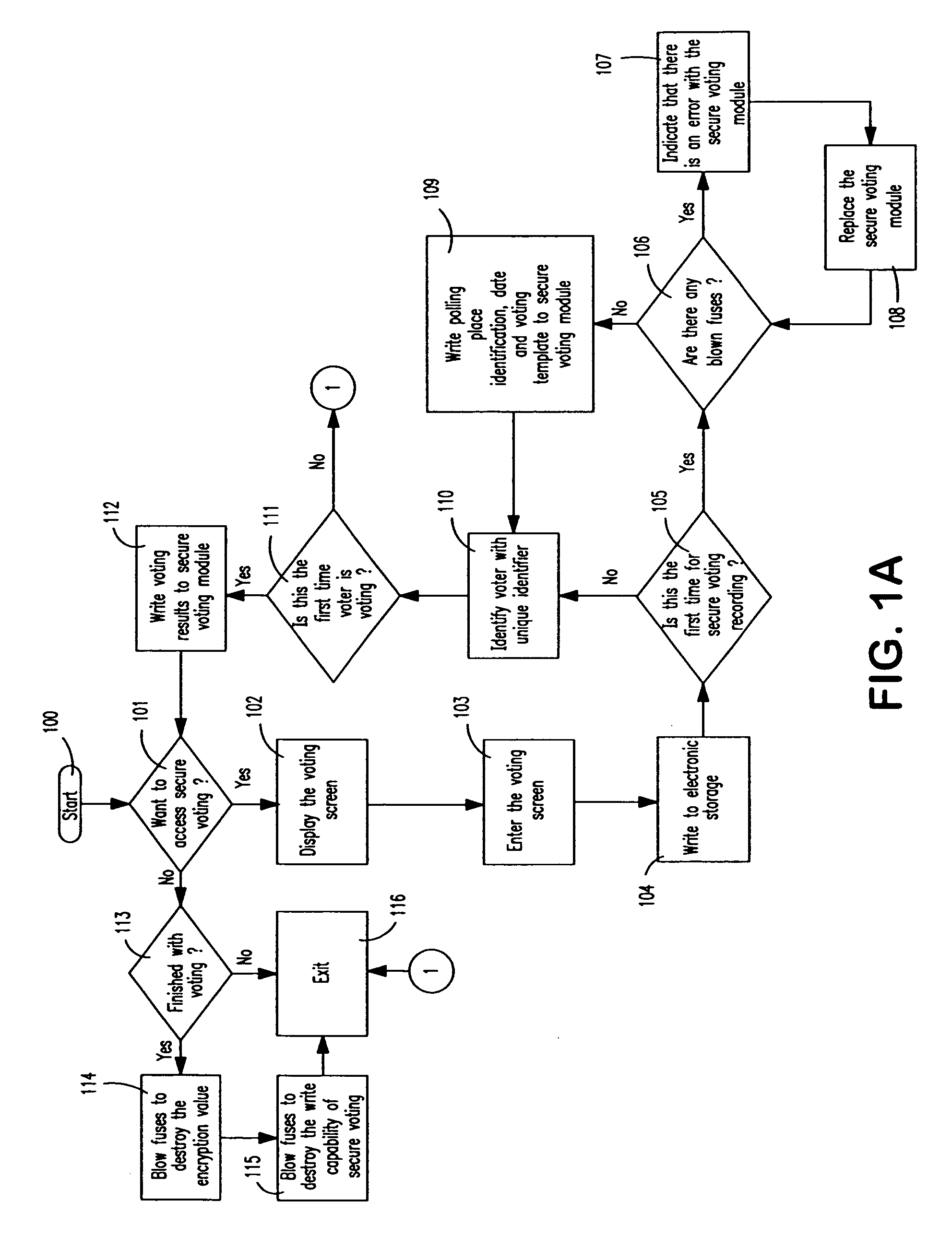
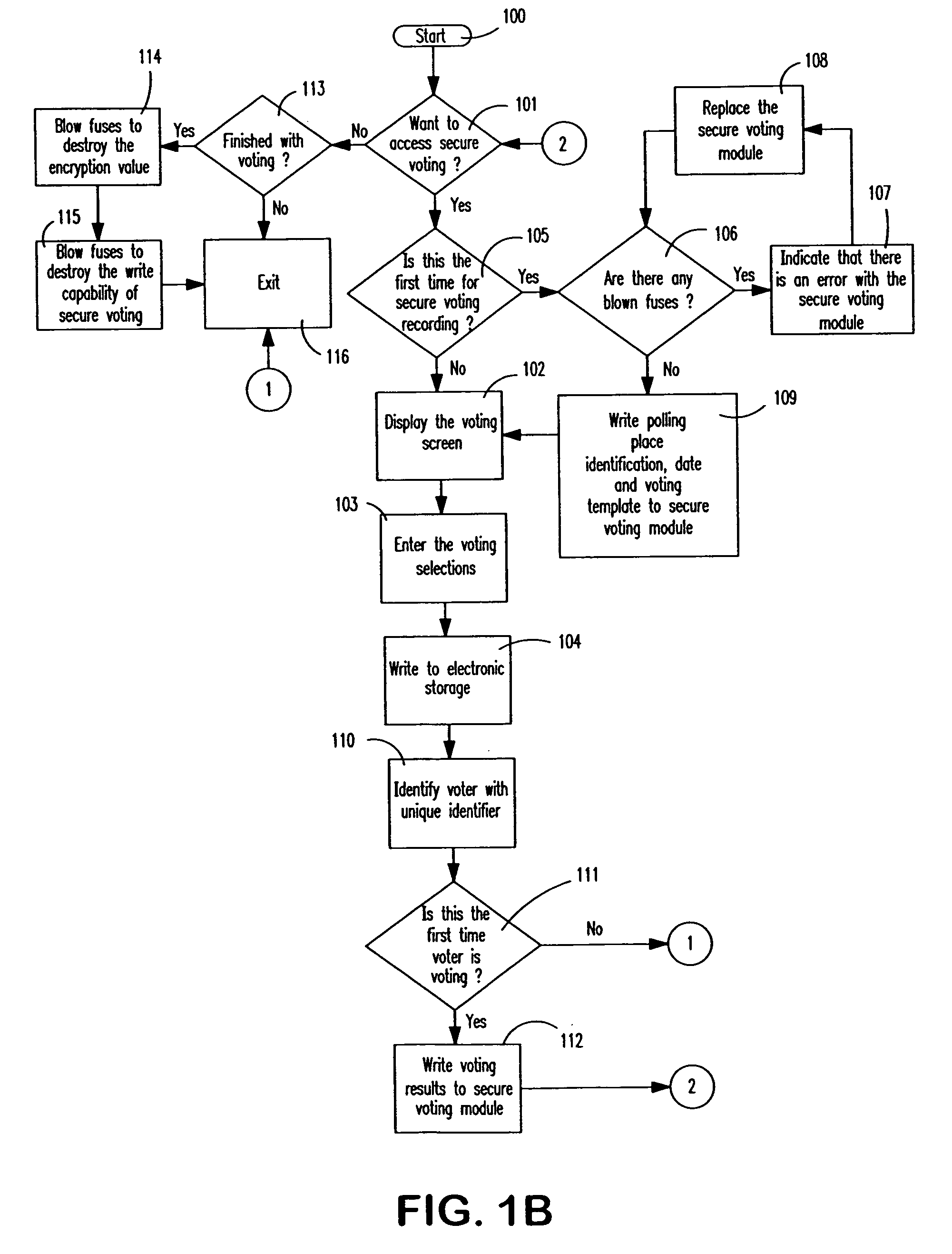
[0026] In describing the preferred embodiments of the present invention, reference will be made herein to FIGS. 1A-2 of the drawings in which like numerals refer to like features of the invention. In the process flows of FIGS. 1A-2, numerals in circles indicate connections to and from other parts of the flow chart.

[0027] The present invention provides methods, systems and apparatus for controlling voting using a computerized secure voting system that employs a transportable, secure voting module. This secure voting module at least contains electronic circuitry including non-replaceable electronic fuses, a memory chip for storage of voting results (e.g. a semiconductor chip), and circuitry for running a software component of the invention. The secure voting module advantageously permanently stores voting results, ensures that a voter securely votes only once and allows for the validation of such voting results.

[0028] The voting module, with its non-replaceable fuses, preferably is ...


PUM


Abstract

Methods, systems and program products for securely voting by providing a secure voting module in communication with a voting device. A voter signs onto the voting device using a unique voter identification, and the voter's voting selections are written to the voting device. A scrambled voter identification is generated using the unique voter identification and a unique encryption value of the secure voting module, whereby the voting selections and the scrambled voter identification are stored in the secure voting module. Once voting has ended, first and second fuses are blown within the secure voting module for destroying the unique encryption value and for permanently storing the voting selections and scrambled voter identification in a read only secure voting module that maintains voter anonymity while preventing any further physically writing thereto. The voting results may then be counted, re-counted or validated.

Description

BACKGROUND OF THE INVENTION [0001] 1. Field of the Invention [0002] The present invention is directed generally to electronic voting, and in particular, to methods, systems and apparatus for controlling voting by using a secure voting system that validates voting results. [0003] 2. Description of Related Art [0004] Voting machines for casting ballots during an election are well known. Conventional types of voting machines include those that make use of paper ballots or mechanical counters. However, many problems exist with these conventional voting machines. For instance, voting machines making use of paper ballots are undesirably subjected to the destruction and / or physical damage of such ballots, or even the possibility of paper ballots being altered. Paper ballots are also undesirable since they are subject to incorrect voting results due to voters punching the wrong holes in the ballots and the cumbersome tasks of reading and tabulating voting results for such paper ballots (par...

Claims


Application Information

Patent Timeline
IPC IPC(8): G07C13/00
CPCG07C13/00
Inventor ANDERSON, JAY H.KELLEY, EDWARD E.MOTIKA, FRANCO
Owner KYNDRYL INC
Why Eureka
Try Eureka