
Signal processing method, image display apparatus, and television apparatus

Inactive Publication Date: 2007-03-08
CANON KK
View PDF13 Cites 47 Cited by
  • Summary
  • Abstract
  • Description
  • Claims
  • Application Information

AI Technical Summary

Benefits of technology

[0019] In the conventional display of three primary colors, one pixel is composed of three sub-pixels of different colors, so that each signal level of three sub-pixels may be decided from the inputted three primary colors. In this case, the signal levels of three sub-pixels (the intensity of the color of each sub-pixel) can be uniquely decided depending on the inputted three primary signals. In the case of composing one pixel of four or more sub-pixels of different colors, it is not always true that a solution is uniquely decided upon calculation of a signal level of four or more sub-pixels from the inputted three primary colors' signals. The inventors of the present invention found that the existence of the unlighted sub-pixel might cause a visual interception in the display to obtain the image by composing a pixel arranging the sub-pixels corresponding to the different colors on a area. Then, they found that the visual interception could be prevented by lighting more sub-pixels within one pixel. In addition, in each of the sub-pixels, its property is changed in accordance with a history of its lighting. This may cause a difference of a property between a sub-pixel of which total lighting time is long and a sub-pixel of which lighting time is short (for example, a difference of a luminance when the same signal drives the sub-pixel). The inventers of the present invention found that the difference of the property between the sub-pixels are not caused easily in the long term by displaying a color designated by the inputted signal lighting more sub-pixels. Each sub-pixel is driven by a signal to specify an intensity of a color of the sub-pixel, so that it is possible to obtain an advantage that the visual interception is decreased by performing the signal processing, whereby the signal to designate the intensity of each color does not easily become 0, or an advantage that a property difference in the long term is prevented.

Problems solved by technology

However, the matrix Mn is a matrix of 3×n, so that the inverse matrix thereof cannot be directly obtained.

Method used


Image

  • Signal processing method, image display apparatus, and television apparatus
  • Signal processing method, image display apparatus, and television apparatus
  • Signal processing method, image display apparatus, and television apparatus

Examples


first embodiment

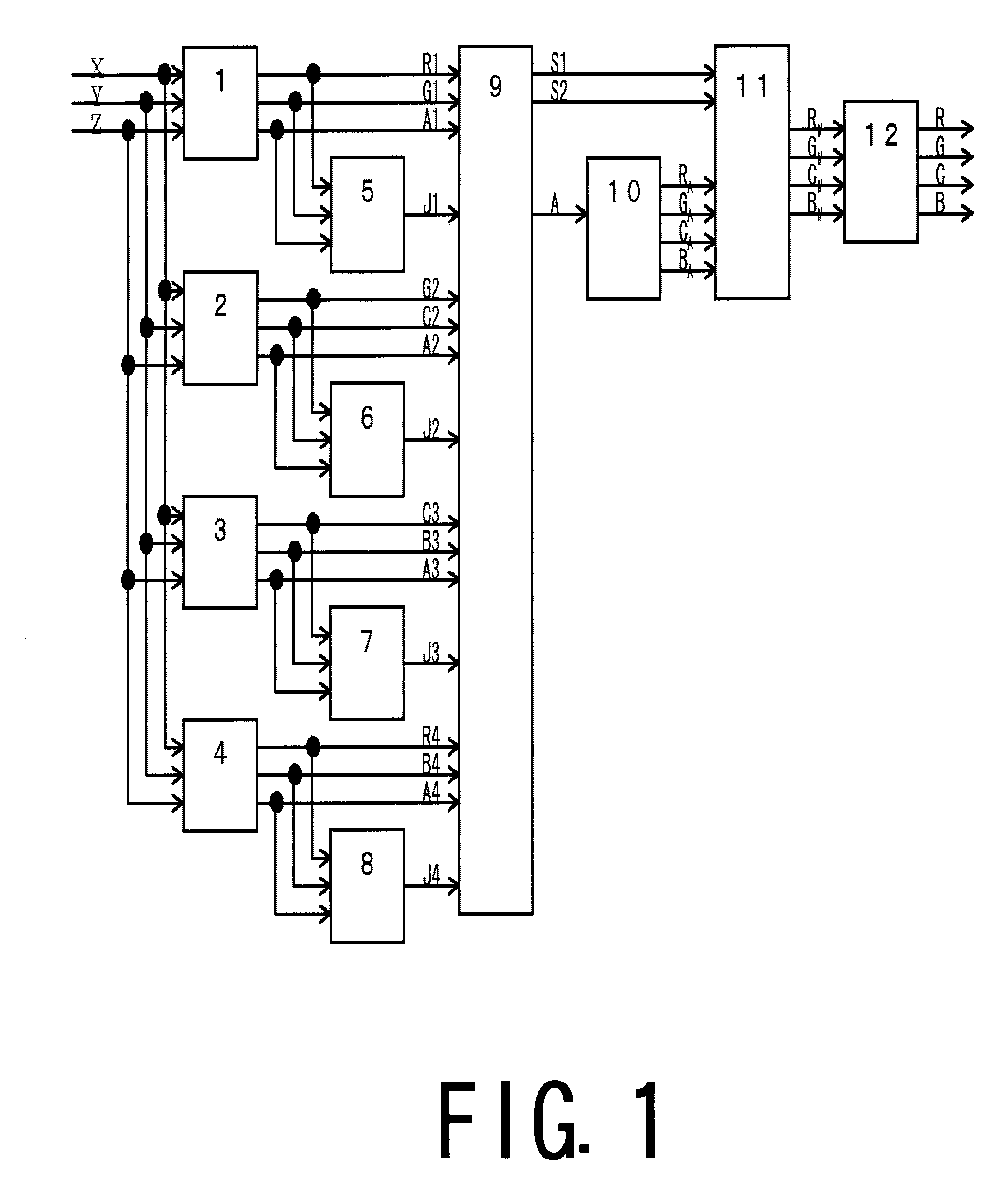
[0050] In the display using the present embodiment, one pixel is composed of four colors (four sub-pixels) which are different from each other. Here, respective colors are R (red), G (green), C (cyan) and B (blue). However, each color of the sub-pixel is not limited to a combination of these colors. Hereinafter, each color of the sub-pixels is referred to as a primary color. In a XYZ chromaticity coordinate at the highest lighting of each primary color, R is defined as (XR, YR, ZR), G is defined as (XG, YG, ZG), C is defined as (XC, YC, ZC), and B is defined as (XB, YB, ZB). A mixed color obtained by synthesizing four primary colors in a mixture ratio (k, l, m, n) is defined as A (XA, YA, ZA) and the mixed color is defined by “Mathematical Expression 5” (corresponding to “a linear type combination” of the present invention). A mixed color A is converted into a plurality of primary colors by “Mathematical Expression 10”. Therefore, it is preferable that the mixed color A is a color o...

second embodiment

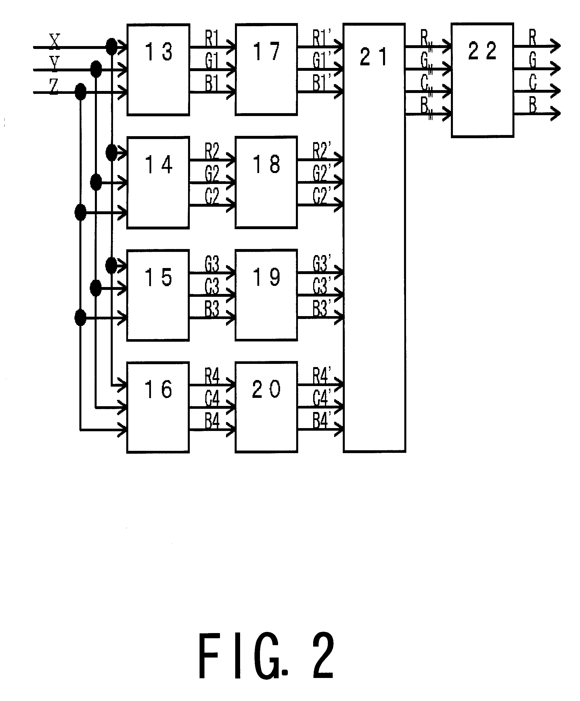
[0060] The example of the display according to the present embodiment that one pixel is composed of four primary colors, R, G, C, and B will be described below. It is assumed that R is (XR, YR, ZR), G is (XG, YG, ZG), C is (XC, YC, ZC) and B is (XB, YB, ZB) in the XYZ chromaticity coordinate.

[0061] Here, in the case of displaying an arbitrary color D in the XYZ chromaticity coordinate (XD, YD, ZD) using four primary colors, the matrix calculation will be made with respect to the all combinations of three primary colors in four primary colors, namely, (RGC, GCB, RCB, RGB). With respect to each of four combinations, three coefficients for displaying the color D by three primary colors are obtained (Mathematical Expressions 12 to 15). Thereby, four combinations of the different three primary colors can be obtained. (r21g21c21)=(XRXGXCYRYGYCZRZGZC)-1·(XDYDZD)<Mathematical⁢ ⁢Expression⁢ ⁢12>(g22c22b22)=(XGXCXBYGYCYBZGZCZB)-1·(XDYDZD)<Mathematical⁢ ⁢Expression⁢ ⁢13>(r23c23b2...

third embodiment

[0076] According to the first and second embodiments, the coefficient of any of four primary colors R, G, C, and B may exceed 1 depending on the value of the mixed color A and the value of the color D. In this case, seeking a difference between 1 and the value of the coefficient exceeding 1 and representing the difference by other primary color, the coefficients of all primary colors can take the values from 0 to 1. For example, when the value of the coefficient of the primary color R is “1.1”, a difference between “1.1” and “1”, namely, “0.1” will be replaced with the coefficient of other three primary colors.

[0077] At first, the coefficient of the primary color when each primary color is represented by other three primary colors is obtained in advance. “Mathematical Expression 17” is a mathematical expression when R is represented by G, C, and B; “Mathematical Expression 18” is a mathematical expression when G is represented by R, C, and B; “Mathematical Expression 19” is a mathe...


PUM


Abstract

A signal processing method comprises the steps of: inputting three signals specifying a color of one pixel; and generating four signals from the input three signals, wherein each of said four signals represents intensities of four different colors to display a color of one pixel by mixing colors, wherein said generating step includes a first converting step of converting the input three signals to two signals representing intensities of two colors among the four colors and a signal representing intensity of a mixed color obtained by mixing (a) the four colors or (b) a plurality of colors among the four colors; and a second converting step of converting the signal representing intensity of the mixed color to a plurality of signals representing intensities of a plurality of colors including at least other two colors different from the two colors.

Description

BACKGROUND OF THE INVENTION [0001] 1. Field of the Invention [0002] The present invention relates to a signal processing method of generating four signals representing intensities of four different colors to represent a color of one pixel from three signals designating a color of one pixel by mixing colors, an image display apparatus, and a Television apparatus. [0003] 2. Description of the Related Art [0004] Conventionally, a display such as a TV set or a computer display monitor has displayed an image by using a light's three primary colors. In other words, various colors can be represented in such a manner that a pixel is composed of each sub pixel of Red (R), Green (G), and Blue (B) and the intensities of the lights of R, G, and B are changed using principles of a parasynthetic mixed color and an additive mixed color. The colors capable of being reproduced by this display is within a range that can be represented by a sum represented by a vector of three primary colors, R, G, an...

Claims


Application Information

Patent Timeline
IPC IPC(8): H04N9/64
CPCH04N9/67
Inventor OSAWA, SEIJIHIRAKI, YUKIOKANAI, IZUMIINAMURA, KOHEITADA, MASARUHOSHI, NOBUHIRO
Owner CANON KK
Learn More