Image forming apparatus having an improved developer conveying system

a technology of conveying system and forming apparatus, which is applied in the direction of electrographic process apparatus, instruments, optics, etc., can solve the problems of deteriorating carrier in time, requiring a large pump, and requiring a strong and large power supply

Inactive Publication Date: 2007-03-08
RICOH KK
View PDF27 Cites 40 Cited by
  • Summary
  • Abstract
  • Description
  • Claims
  • Application Information

AI Technical Summary

Problems solved by technology

Therefore, the carrier deteriorates in time.
Even when the image forming apparatus uses an-air pump to convey the carrier through the inclined path against gravity, a conveying failure may still occur because a specific gravity of the carrier is larger than a specific gravity of the toner.
As a result, a strong and large pump requiring a high power may be needed.

Method used


Image

  • Image forming apparatus having an improved developer conveying system
  • Image forming apparatus having an improved developer conveying system
  • Image forming apparatus having an improved developer conveying system

Examples


Embodiment Construction

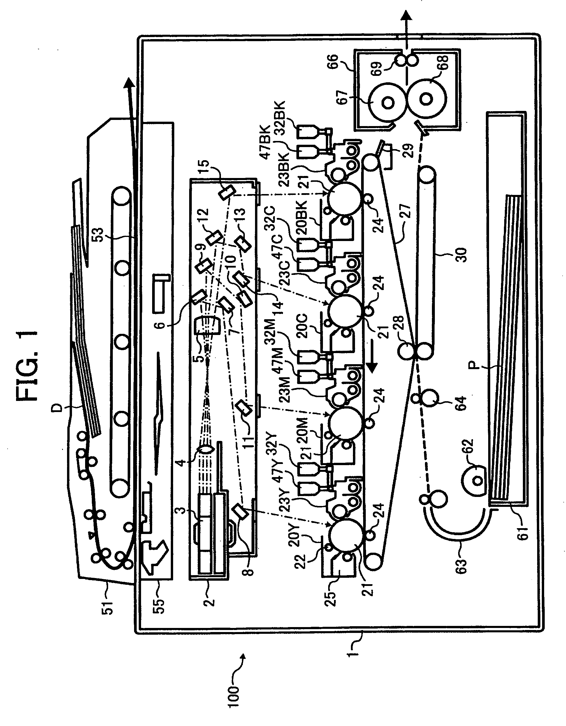
[0026] In describing preferred embodiments illustrated in the drawings, specific terminology is employed for the sake of clarity. However, the disclosure of this patent specification is not intended to be limited to the specific terminology so selected and it is to be understood that each specific element includes all technical equivalents that operate in a similar manner. Referring now to the drawings, wherein like reference numerals designate identical or corresponding parts throughout the several views, particularly to FIG. 1, an image forming apparatus 100 according to an embodiment of the present invention is described.

[0027]FIG. 1 illustrates an image forming apparatus 100 according to an embodiment of the present invention. In FIG. 1, a color copier is shown as an example of the image forming apparatus. As illustrated in FIG. 1, the image forming apparatus 100 includes a main body 1, a writing unit 2, color process cartridges 20Y, 20M, 20C and 20 BK, photosensitive drums 21,...


PUM


Abstract

An image forming apparatus includes a conveying pipe configured to convey a developer and a magnetic field generation mechanism configured to generate a magnetic field inside the conveying pipe to affect the developer. The magnet is formed to have lower magnetic intensities at positions upstream and downstream from a middle position of the conveying pipe along a conveying direction of the conveying pipe than a magnetic intensity in the middle of the conveying pipe.

Description

[0001] This patent application is based on Japanese patent applications No. 2005-258644 filed on Sep. 7, 2005 and No. 2006-172536 filed on Jun. 22, 2006 in the Japan Patent Office, the entire contents of which are incorporated by reference herein. BACKGROUND OF THE INVENTION [0002] 1. Field of the Invention [0003] The present invention relates to an image forming apparatus, and more particularly to an image forming apparatus which is capable of stably and efficiently conveying a developer along an inclined conveying pipe. [0004] 2. Discussion of the Background [0005] Background image forming apparatuses, such as printers, facsimiles, copiers, and multifunction apparatuses which print, fax, copy, and so on generally use an electrophotographic process for image forming. Such background image forming apparatus includes a development unit which employs a trickle development method to supply a new carrier. [0006] Using the trickle development method, the new carrier is supplied by a nece...

Claims


Application Information

Patent Timeline
Patent Type & Authority Applications(United States)
IPC IPC(8): G03G15/08
CPCG03G2215/0607G03G15/0877G03G15/0879G03G2215/0802
Inventor IWATA, NOBOUMATSUMOTO, JUNICHIICHIKAWA, TOMOYUKIKATOH, NATSUMI
Owner RICOH KK
Why Eureka
Try Eureka