Fan duct

a technology of fan ducts and ducts, applied in the direction of electrical apparatus construction details, semiconductor/solid-state device details, instruments, etc., can solve the problems of large heat generation of electronic components, easy loss of screws, and large heat generation of central processing units of computers. achieve the effect of improving the overall appearance of the casing

Inactive Publication Date: 2007-03-15
UNIVERSAL SCI IND CO LTD
View PDF23 Cites 18 Cited by
  • Summary
  • Abstract
  • Description
  • Claims
  • Application Information

AI Technical Summary

Benefits of technology

[0009] The primary object of the invention is therefore to specify a fan duct that is capable of being mounted on and ...

Problems solved by technology

When an electronic product operates, its electronic components generate a large amount of heat.
For example, a central processing unit of a computer processes data at a very fast speed and generates a large amount of heat.
Furthermore, when detac...

Method used


Image

  • Fan duct
  • Fan duct
  • Fan duct

Examples


Embodiment Construction

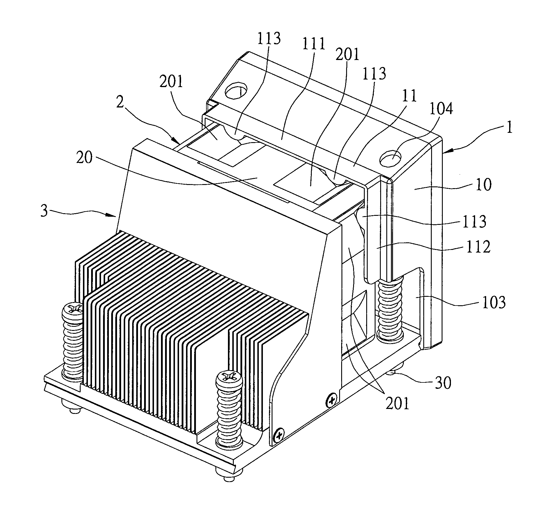
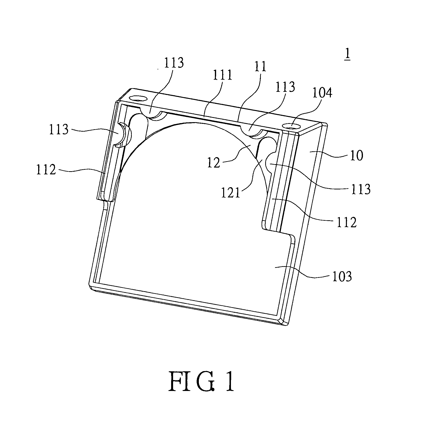
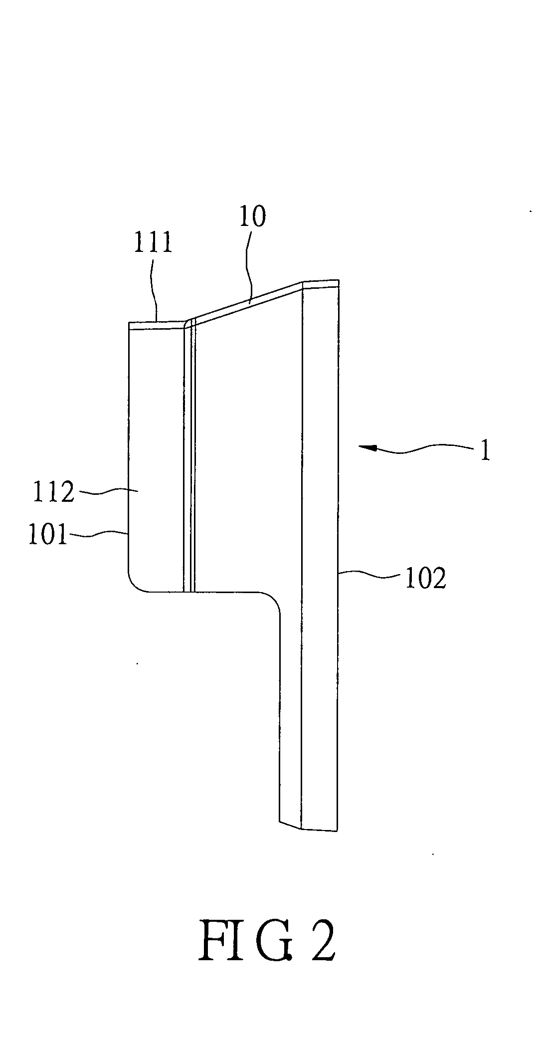
[0024]FIG. 1 and FIG. 2 show a first embodiment of the present invention. The present invention provides a fan duct 1. Referring to FIGS. 3-5, the fan duct 1 is retained on a fan 2. The fan duct 1 comprises a main duct wall 10, a connecting wall 11, and an inner baffle 12.

[0025] The main duct wall 10 has a fan-end opening 101 adjacent to the fan 2 and a casing-end opening 102 adjacent to a casing (not shown). The main duct wall 10 further forms a cutout 103 in a bottom portion of the fan-end opening 101. The main duct wall 10 further has a through hole 104 disposed in an upper portion thereof.

[0026] The connecting wall 11 extends axially and outwardly from the fan-end opening 101 of the main duct wall 10. As shown in FIG. 1, the connecting wall 11 has an upper wall 111 and two lateral walls 112. In addition, the connecting wall 11 has at least two hooks 113 extending radially toward the fan-end opening 101. In the first embodiment, the at least two hooks 113 have a quantity of fou...


PUM


Abstract

A fan duct is retained on a fan. The fan has an outer frame. The outer frame forms a plurality of cavities in an outer circumferential surface thereof. The fan duct has a main duct wall and a connecting wall. The main duct wall has a fan-end opening. The connecting wall extends outwardly from the fan-end opening of the main duct wall and has at least two hooks. An edge of the outer circumferential surface of the outer frame of the fan matches an inside of the connecting wall, and each of the hooks locks into a corresponding one of the cavities. As a result, the fan duct of the present invention is capable of being easily hung onto the fan, so that the fan duct can be mounted on and detached from the fan without requiring the use of tools.

Description

BACKGROUND OF THE INVENTION [0001] 1. Field of the Invention [0002] The present invention relates to a fan duct, and more particularly, to a fan duct for a heat dissipation module of an electronic product. [0003] 2. Background of the Invention [0004] When an electronic product operates, its electronic components generate a large amount of heat. The heat has to be dissipated to reduce the temperature of the electronic components, thereby ensuring that the operations of the electronic components are normal. For example, a central processing unit of a computer processes data at a very fast speed and generates a large amount of heat. The heat has to be dissipated quickly to prevent the computer from crashing. Therefore, an electronic product requires a heat dissipation module to dissipate heat for its electronic components. [0005] A conventional heat dissipation module includes a heat dissipation device (such as a set of heat dissipation fins) and a fan. The fan is mounted on the heat d...

Claims


Application Information

Patent Timeline
IPC IPC(8): H05K7/20
CPCG06F1/20H01L23/4006H01L23/467H01L2023/4081H01L2924/0002H05K7/20172H01L2924/00
Inventor HSIAO, TSUNG-TE
Owner UNIVERSAL SCI IND CO LTD
Why Eureka
Try Eureka