Automatic ground marking method and apparatus

a technology of automatic ground marking and apparatus, applied in the direction of roads, construction, skiing, etc., can solve the problems of time-consuming and labor-intensive production and application of stencils for creating complex and large turf markings, prone to error, and distortion of logos

Inactive Publication Date: 2007-03-15
MAYFIELD IAN +1
View PDF5 Cites 40 Cited by
  • Summary
  • Abstract
  • Description
  • Claims
  • Application Information

AI Technical Summary

Benefits of technology

[0009] Briefly described, in architecture, one embodiment of the system, among others, can be implemented as follows. An automatic ground marking apparatus including a carriage responsive to carriage control signals for traversing the ground, the carriage having a controllable steering and drive system, a controllable marking system and a position determining system arranged to determine the position of the carriage. The ground marking apparatus further includes a processor responsive to the position determining system and operatively executing a software product for generating said carriage control signals to cause the ca

Problems solved by technology

Line marking machines are not suitable for producing complex signs or logos on turf.
The production and application of stencils for creating complex and large turf markings is time consuming and prone to error.
Large variations or undulat

Method used


Image

  • Automatic ground marking method and apparatus
  • Automatic ground marking method and apparatus
  • Automatic ground marking method and apparatus

Examples


Embodiment Construction

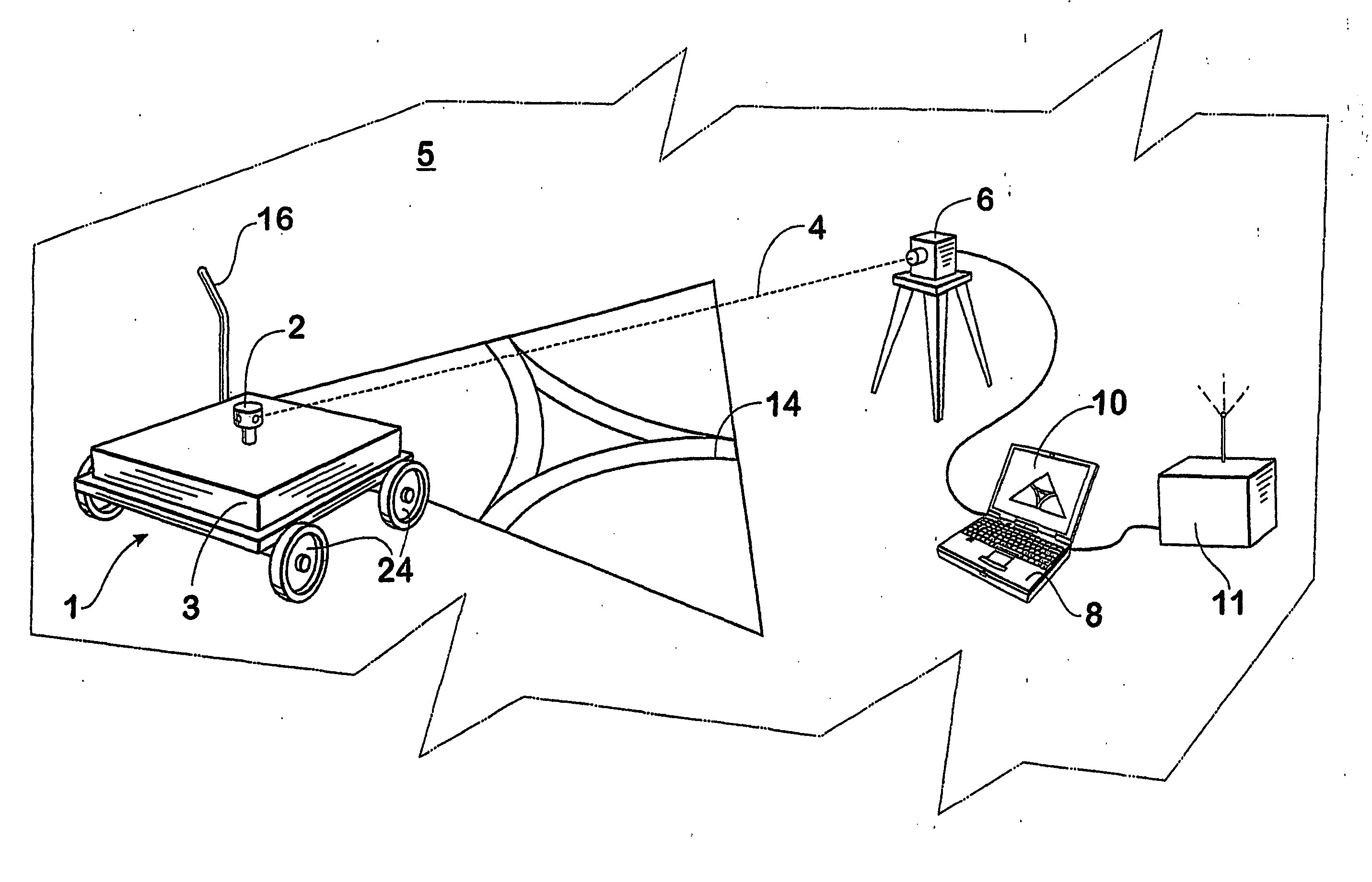
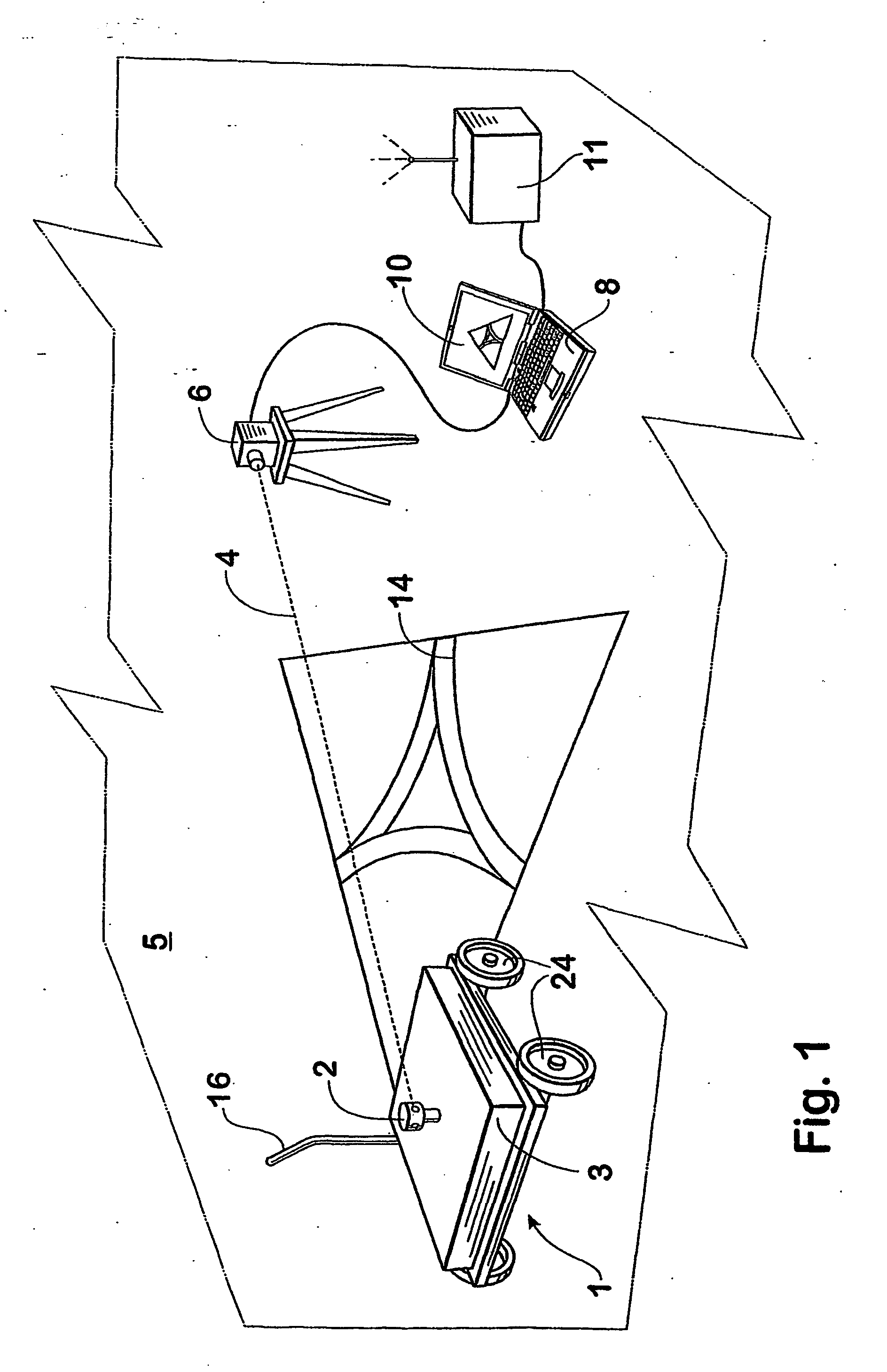
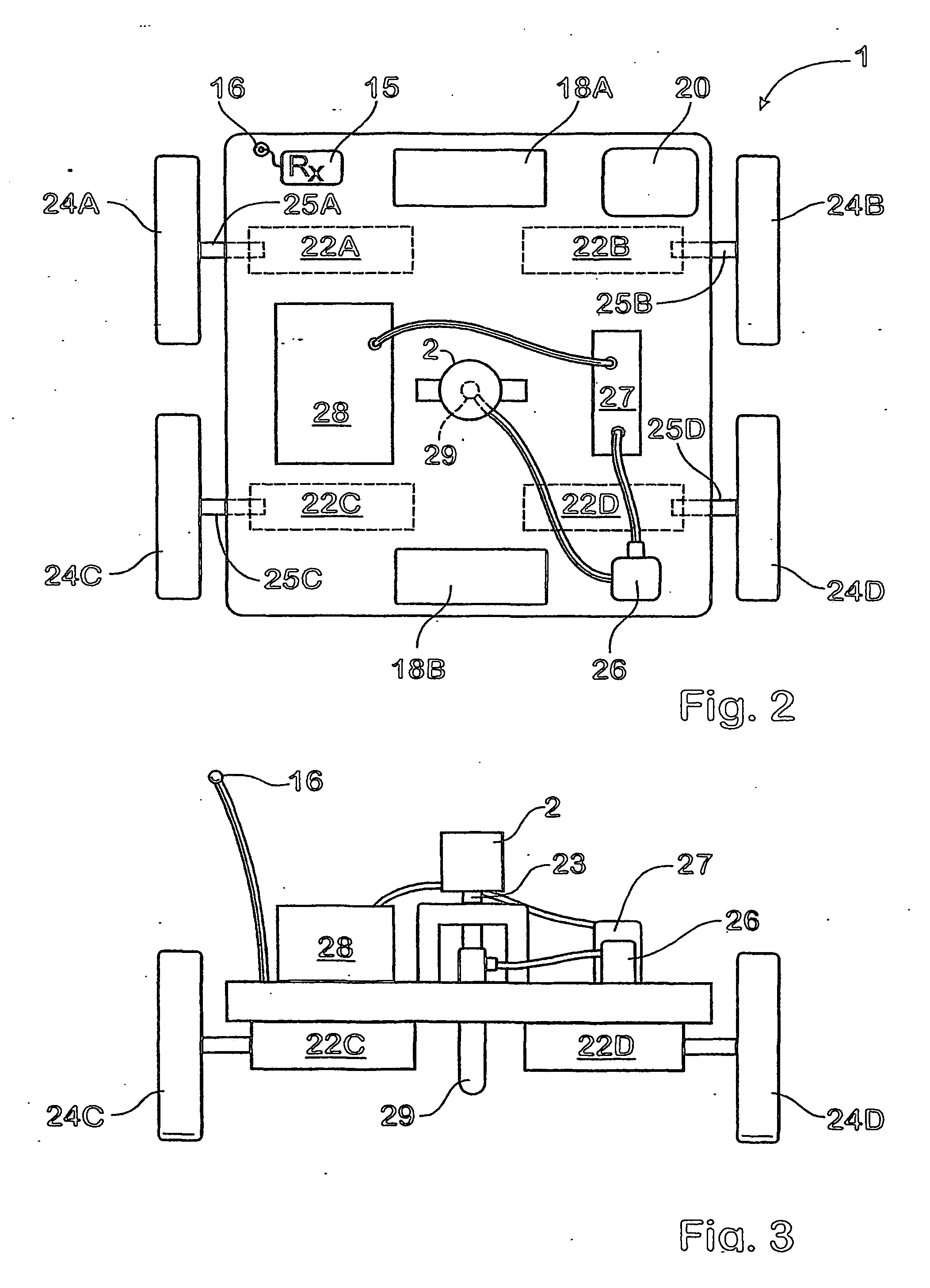
[0024] According to a first aspect of the invention there is provided an automatic ground marking apparatus including: a carriage responsive to carriage control signals for traversing the ground, the carriage having a controllable steering and drive system and a controllable marking system; a position determining system arranged to determine the position of the carriage; and a processor responsive to the position determining system and operatively executing a software product for generating said carriage control signals wherein the controllable steering and drive system respond to said carriage control signals to cause the carriage to traverse the ground and mark out a predetermined sign on the ground.

[0025] In the present specification, the term “position” includes position of an object in three dimensional (3D) space, including the latitude, longitude and height of the object relative to a predetermined point of reference. If required, the carriage control signals are transmitted...


PUM


Abstract

An automatic ground marking apparatus including a carriage (1) responsive to carriage control signals for traversing the ground (5), the carriage having a controllable steering and drive system, a controllable marking system and a position determining system (6) arranged to determine the position of the carriage. The ground marking apparatus further includes a processor (8) responsive to the position determining system and operatively executing a software product for generating said carriage control signals to cause the carriage (1) to mark out a predetermined sign (14) on the ground.

Description

CROSS-REFERENCE TO RELATED APPLICATION [0001] This application is a continuation-in-part of copending U.S. utility application entitled, “AUTOMATIC GROUND MARKING METHOD AND APPARATUS,” having Ser. No. 10 / 669,555, filed Sep. 25, 2003, and PCT application entitled, “AUTOMATIC GROUND MARKING METHOD AND APPARATUS” having appl. no. PCT / AU02 / 00357, filed Mar. 25, 2002, both of which are incorporated herein by reference in their entirely.TECHNICAL FIELD [0002] The present invention relates to an apparatus and method for making markings on ground surfaces such as turf playing fields and fairways. The invention has particular although not exclusive application where there is a need to automatically produce signs, such as logos or advertisements for example, on large ground surfaces whether even, sloped or undulating. BACKGROUND OF THE INVENTION [0003] A variety of arrangements for marking turf, such as the turf of playing fields, are known in the prior art. The simplest turf marking involve...

Claims


Application Information

Patent Timeline
IPC IPC(8): E01C23/07
CPCE01C23/163A63C19/06G05D1/0236G05D1/028
Inventor MAYFIELD, IANJOHNSON, MATTHEW
Owner MAYFIELD IAN
Why Eureka
Try Eureka